

Home Automation using Arduino and ESP8266 Module
Contents
In this project we are going to make a home automation system using ESP8266 WiFi module and Arduino Uno. Using this we will be able to control lights, electric fan and other home appliances through a web browser using your PC or mobile. These AC mains appliances will be connected to relays which are controlled by the Arduino. ESP8266 and Arduino together acts as a Web Server and we will send control commands through a Web Browser like Google Chrome or Mozilla Firefox. ESP8266 is the one of the most popular and low cost wifi module available in the market today. You can ready more about it here, ESP8266 – WiFi SoC.
ESP-01 ESP8266 Module
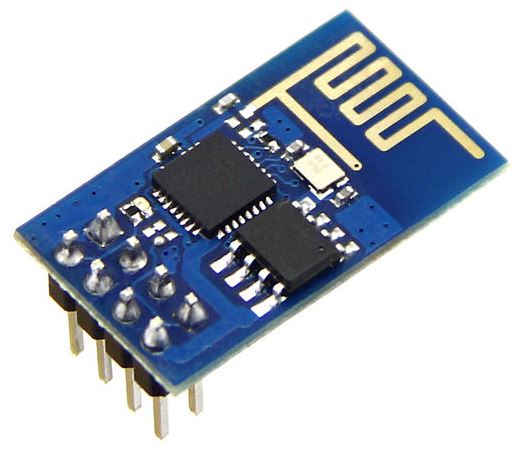
ESP-01 is the one of the most popular ESP8266 module available in the market. ESP8266 is a self contained SoC with integrated TCP/IP stack which helps any microcontroller having UART to access a wifi network. It can act as both WiFi access point as well as a WiFi client. It is pre-programmed with AT commands, so we can easily access and configure it using a microcontroller.
ESP8266 runs on 3.3V and its input pins are not 5V tolerant. So we need to reduce the 5V output of the Arduino Tx pin to 3.3V by using voltage dividing resistors to connect to Rx pin of ESP8266 module. Arduino TTL input pins will detect 3.3V as logic high, so we can directly connect 3.3V output of ESP8266 Tx to Arduino Rx pin.
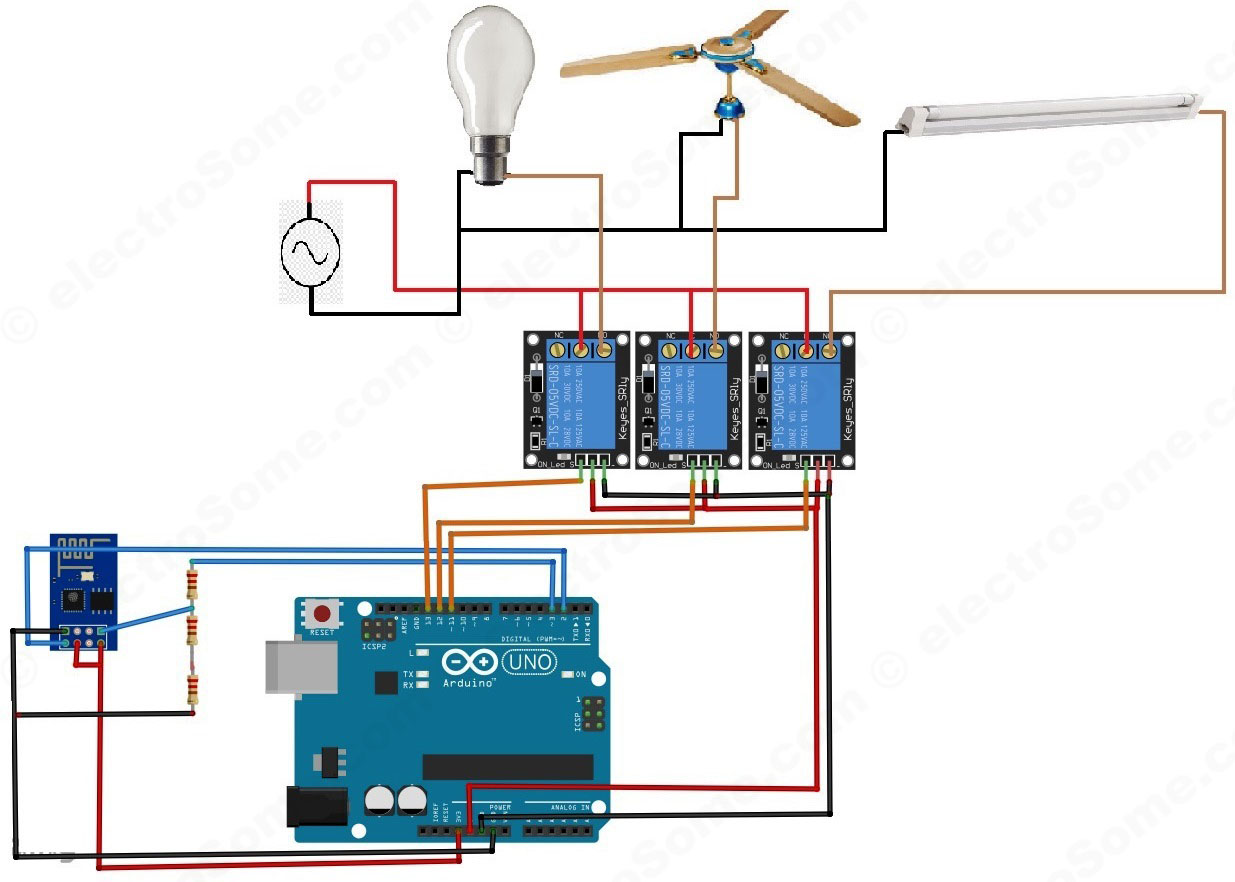
Circuit Diagram and Explanation
First we can connect ESP8266 with the Arduino Uno. The ESP8266 runs on 3.3V, it may damage if you connect it directly to 5V from Arduino. The pin out of the ESP-01 ESP8266 module is shown below.
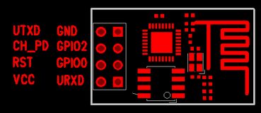
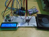
Connect the VCC and CH_PD of the ESP8266 to the 3.3V output pin of Arduino. CH_PD is Chip Power Down pin, which is active low. So we will give 3.3V to it, which will enable the chip. Then connect the TXD pin of the ESP8266 with the digital pin 2 of the Arduino. Then make a voltage divider to make 3.3V for the RXD of the ESP8266 which is connected to the pin 3 of Arduino. Here we are using software UART through digital pins 2 & 3 of Arduino. Lastly, connect the ground of the ESP8266 with the ground of the Arduino.
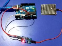
Now we can connect relays to Arduino. Connect three relays to pins 11, 12 and 13 of the Arduino. Also connect 5V and ground from the Arduino to power the relay. Note that here I am using relay modules which having built in transistor driver. So don’t forget to add driver when you are using bare relays. We can connect AC devices to the output terminals of those relays. First connect one wire (Phase) of the AC source with the common terminal (COM) of all relays and the second wire (Neutral) of AC source to one terminal of AC devices. Then connect the other terminal of AC devices to the NO (Normally Open) terminal of relays.
Program
Arduino Sketch
#include <SoftwareSerial.h>  //Including the software serial library
#define DEBUG true
SoftwareSerial esp8266(2,3); // This will make the Arduino pin 2 as the RX pin and Arduino pin 3 as the TX. Software UART
/* So you have to connect the TX of the esp8266 to the pin 2 of the Arduino and the TX of the esp8266 to the pin 3 of the Arduino. This means that you need to connect the TX line from the esp to the Arduino's pin 2 */

void setup()
{
  Serial.begin(9600);   // Setting the baudrate to 9600
  esp8266.begin(9600);  // Set it according to your esp’s baudrate. Different esp’s have different baud rates.
  pinMode(11,OUTPUT);   // Setting the pin 11 as the output pin.
  digitalWrite(11,LOW); // Making it low.
  pinMode(12,OUTPUT);   // Setting the pin 12 as the output pin..
  digitalWrite(12,LOW); // Making pin 12 low.
  pinMode(13,OUTPUT);   // Setting the pin 13 as the output pin.
  digitalWrite(13,LOW); // Making pin 13 low.
  sendData("AT+RST\r\n",2000,DEBUG);            //This command will reset module to default
  sendData("AT+CWMODE=2\r\n",1000,DEBUG);       // This will configure the mode as access point
  sendData("AT+CIFSR\r\n",1000,DEBUG);          // This will get ip address and will show it
  sendData("AT+CIPMUX=1\r\n",1000,DEBUG);       // This will configure the ESP8266 for multiple connections
  sendData("AT+CIPSERVER=1,80\r\n",1000,DEBUG); // This will set the server on port 80
}
void loop()
{
  if(esp8266.available()) // Checking that whether the esp8266 is sending a message or not (Software UART Data)
  {
    if(esp8266.find("+IPD,"))
    {
      delay(1000);        // Waiting for 1 sec
      int connectionId = esp8266.read()-48;   // Subtracting 48 from the character to get the number.
      esp8266.find("pin=");                   // Advancing the cursor to the "pin="
      int pinNumber = (esp8266.read()-48)*10; // Getting the first number which is pin 13
      pinNumber += (esp8266.read()-48);       // This will get the second number. For example, if the pin number is 13 then the 2nd number will be 3 and then add it to the first number
      digitalWrite(pinNumber, !digitalRead(pinNumber)); // This will toggle the pin
      // The following commands will close the connection
      String closeCommand = "AT+CIPCLOSE=";
      closeCommand+=connectionId;
      closeCommand+="\r\n";
      sendData(closeCommand,1000,DEBUG);     // Sending the data to the ESP8266 to close the command
    }
  }
}
String sendData(String command, const int timeout, boolean debug) // Function to send the data to the esp8266
{
  String response = "";
  esp8266.print(command);           // Send the command to the ESP8266
  long int time = millis();
  while( (time+timeout) > millis()) // ESP8266 will wait for some time for the data to receive
  {
    while(esp8266.available())      // Checking whether ESP8266 has received the data or not
    {
      char c = esp8266.read();      // Read the next character.
      response+=c;                  // Storing the response from the ESP8266
    }
  }
  if(debug)
  {
    Serial.print(response);         // Printing the response of the ESP8266 on the serial monitor.
  }
  return response;
}
Explanation
The code is very long but easy to understand as it is well commented. First we will initialize the software uart with digital pins 2 & 3 of Arduino for the communication with ESP8266. After that we will initialize pins to which we will connect relays as output pins. Then we will configure ESP8266 in access point mode. Arduino + ESP8266 is programmed as a web server such that we can control those relays through a web browser.
HTML Code
<html>
<head>
<title>Home Automation System</title>  <!-- This will be the page title -->
</head>
<body> <!-- All the data in it will be shown on the page -->
<button id="11" class="led">Toggle Pin 11</button> <!--  This will create the button for pin 11 -->
<button id="12" class="led">Toggle Pin 12</button> <!--  This will create the button for pin 12 -->
<button id="13" class="led">Toggle Pin 13</button> <!--  This will create the button for pin 13 -->

<script src="jquery.min.js"></script> <!-- This will read the script from the jquery -->
<script type="text/javascript">
$(document).ready(function(){
  $(".led").click(function(){
    var p = $(this).attr('id'); // Getting the id value that which pin to toggle, pin 13 or pin 13 or pin 11
    // Sending the request to the ip address of the server with the pin number to toggle the pin
    $.get("http://192.168.4.1:80/", {pin:p}); // Sending the get request
  });
});
</script>
</body>
</html>
jQuery
The above HTML code uses the open source javascript library JQuery, so we need to obtain that. You can get it from this link and save it by right clicking on it. Save it in the same directory where you are going to save the above HTML code. Save the JQuery library file as the jquery.min and the full name of the file will be “jquery.min.js”.
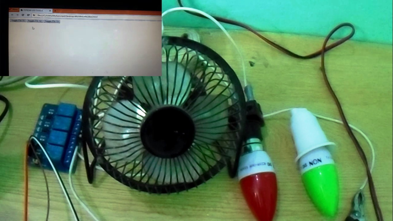
Then copy above HTML code in a file and save it as an HTML file, say ‘control.html’. You can open this HTML file in a web browser, which will looks as shown below.

Explanation
Whenever a button is pressed in the web browser, a HTTP GET request is send to the Arduino-ESP8266 webserver to toggle a particular pin. In the Arduino code, it looks for the string “+IPD” again and again to check that if any request is coming or not. When it gets a request it reads the next character which is the connection id. Connection id is required to close the particular TCP connection after processing the request. Then it looks for the pin number to toggle by checking the character after the string “?pin=”. The Arduino then toggles that particular digital pin, which toggles the relay.
How to make it work ?
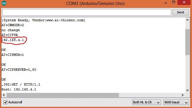
After uploading the code to the Arduino, open the serial monitor from the Arduino IDE. It will show you the IP address as shown below.
First connect your system to the access point created by ESP8266 module (ESP_xxxxxx). Update the IP address in the control.html file created above. Now open the file using your web browser (Google Chrome or Mozilla Firefox). Now you can control your home appliances very easily.
Note : You may change the default SSID (ESP_xxxxxx) of ESP8266 WiFi module by using AT+CWSAP command.

Did you get the web page on the browser ?
In this code ESP8266 is configured as an access point. So it will create its own WiFi network. Simply connect your laptop or mobile to that WiFi.
Am using my phone to control the leds but it not working
Pls do you need to connect WiFi to your esp8266 module before it works…?
Please post more details about the issue you are facing.
I try it and it’s not working any help?
hi,
I am getting this error:
ssize_t’ does not name a type ssize_t m_swsInstsIdx = -1;
when i try to Verify the above code you have given..Please help to solve ASAP
We are not getting the IP address . Please explain how to get it
give some ideas
sir tell me if controll fan speed externally with regulator at same time ..how can poosible???
hello sir ,
I want to get IP address without using serial PORT . How can we do this. If is it possible . Can we print on Web page.
i am getting the same blank serial monitor…can some help me please…
Hi for me also the serial monitor showing empty…
How you upload the program? Is Esp-01 module need to be program separately and arduino program seperately???
Or Is the given single programm enough?
Can you please explain in detail for programming steps
Instead of using pin number {pin:p} directly in the code i want to activate it by a code. Say when i send “onrelay1” it should activate pin.
E.g 192.168.4.1/?pin=onrelay1
Instead of 192.168.4.1/?pin=11
i must thank you for such a wonderful project. Please can this be used to control relays from as far off as a persons office
hi , I’m working on a senior project which i can control the controller of hdmi switch by using relays and arduino , I connect the wires as the picture above , and copied the arduino code , but there is no output on serial monitor . what is the problem ? thank you .
why my esp does not show anything to serial monitor and also it does not response to any command!
hloo sir,
I executed this programme,but nothing is showing for me on serial monitor.
so what to do..?
Dude how did you solve this problem
https://uploads.disquscdn.com/images/e3d442748079ca056a4a432861aed82e148bae0c306b40044bc580c57192424c.png https://uploads.disquscdn.com/images/2c66cd5e116863bd1d63e0a446e5966e514ef36b94ec5cbbc3ab7bfe8157344a.png
do not come ip address…why ??? arduino program is ok ????
Sir, I getting the Warnings in the Arduiono Sketch.
:My Project FilesAruinoProgram8266sketch_jan08bsketch_jan08b.ino:26:28: warning: deprecated conversion from string constant to ‘char*’ [-Wwrite-strings]
if(esp8266.find(“+IPD,”))
^
Try this : https://electrosome.com/home-automation-bluetooth-mobile-app/
Not Much Explanation…………
no prolem to do this .i also do this mini project
I want to control 8 relays and controll it by android app
it can be controlled by any apps
it can be controlled by any android apps
sir,when a DC source was provided instead of this Ac source by connecting with the DC motor and bulb for an mini level project,did any fault obtained for the design….?.please answer me sir
can html in esp8266?
I faced the same problem
did you solve it?
HI,i had tried this
everything is alright but my esp-01 is not showing anything after opening serial monitor what can i do relays are on when connecting power supply
how to design ESP8266 using protues software?
Can i use a 4 channel relay for this project. (4 Channel 5V Relay Module 10A)
Can you provide details on flashing the esp8266? What do I need to do to get the ESP to connect to my home network?
where u got UART software
Hello, I would like to have a full circuit including the breadboard with its resistors and more on this home automation, anyone please its terribly urgent