

Home Automation using Bluetooth and Mobile App
Contents
Technology is a never ending process. To be able to design a product using the current technology that will be beneficial to the lives of others is a huge contribution to the community.
Generally in today’s modern world human beings are addicted to using modern equipment. So here we can perform home automation by using an Android App and Bluetooth as a wireless communication medium. Home automation not only refers to reduce human efforts but also energy efficiency and time saving. Home Automation System has been designed using PIC 16F876A microcontroller and HC-06 bluetooth module. It can control a number of home appliances like lights, fans, bulbs and many more using electro-mechanical relay.
Components Required
- PIC 16F876A Microcontroller
- HC-06 Bluetooth Module
- ULN2803 Driver IC
- 8x 12V Sugar Cube Relays
- Voltage Regulator IC 7812
- Voltage Regulator IC 7805
- 4x 1N4007 Diode
- 8MHz Crystal
- Red LED
- Orange LED
- 8x Green LED
- 1000uF Capacitor
- 3x 100uF Capacitor
- 10uF Capacitor
- 1uF Capacitor
- 0.1uF Capacitor
- 2x 22pF Capacitor
- 10KΩ Resistor
- 1KΩ Resistor
- 10x 680Ω Resistor
Hardware
Circuit Diagram
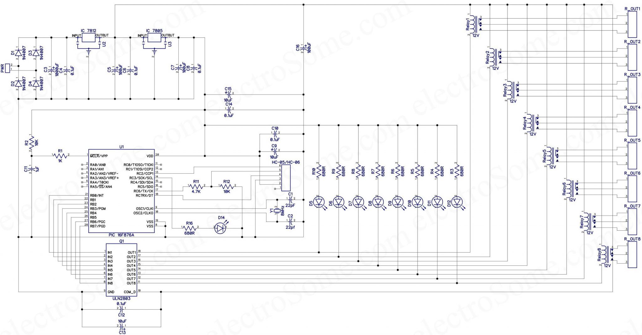
Hope you can easily understand the circuit. PIC 16F876A is the heart of this circuit. Two voltage regulators are used in this circuit. 7812 for providing 12V supply for the operation of relays and 7805 for the operation of the rest of the circuit. ULN2803 driver IC is used to driver relays. HC-05 is operating at 3.3V, but the module which we are using here is having built in 3.3V regulator. Thus we can provider 5V to it. R11 (4.7K) and R12 (10K) are used to reduce the 5V TX output of PIC microcontroller to 3.3V as HC-05 module inputs are not 5V tolerant. 3.3V TX output of HC-05 is directly connected to the RX input of PIC microcontroller. As 3.3V will be taken as LOGIC HIGH as per 5V TTL specifications.
HC-05 Bluetooth Transceiver Module

- HC-05 Bluetooth Transceiver module is used to establish communication between mobile phone and microcontroller.
- HC-05 is low power 1.8V operation and is easy to use with Bluetooth SPP (serial port protocol) and 3Mbps modulation with complete 2.4GHZ radio transceiver and base band.
- The module has two modes of operation, Command Mode where we can send AT commands to it and Data Mode where it transmits and receives data to another Bluetooth module.
| Pin Name | Details |
|---|---|
| KEY | AT Command Mode |
| VCC | 3.3V to 5V |
| GND | Ground |
| TXD | Serial Port Transmit Data |
| RXD | Serial Port Receive Data |
| STATE | Not Connected |
Software
PIC Microcontroller Program
int cnt,t,st;
void interrupt()
{
  if(UART1_Data_Ready())      // If data received
  {
    RCIE_bit = 0;
    if(cnt == 0)              //If it is the first character
    {
      if(UART1_Read() == 'A') // Check whether it is the valid character
      {
        cnt = 1;
        TMR1L = 0;
        TMR1H = 0;
        TMR1ON_bit = 1;       // Start the timer for timing out
      }
    }
    else if(cnt == 1)         // If second character
    {
      t = UART1_Read() - 48;
      cnt++;
    }
    else if(cnt == 2)         // If third character
    {
      st = UART1_Read() - 48;
      cnt++;
    }
    else if(cnt >= 3)         // Clear if count is greater than 2
    {
      cnt = 0;
      TMR1ON_bit = 0;
      TMR1L = 0;
      TMR1H = 0;
    }
    RCIE_bit = 1;
  }
  else if(TMR1IF_bit == 1)   // UART Timeout
  {
    TMR1IE_bit = 0;
    TMR1IF_bit = 0;
    TMR1H = 0;
    TMR1L = 0;
    cnt = 0;
    TMR1IE_bit = 1;
  }
}

void main()
{
  TRISB = 0x00;   // Make all PORTB pins output
  PORTB = 0x00;   // Turn off All relays

  GIE_bit = 1;    // Global Interrupt Enable
  PEIE_bit = 1;   // Peripheral Interrupt Enable
  RCIE_bit = 1;   // UART Interrupt Enable
  T1CON = 0x30;   // Configure Timer 1
  TMR1IE_bit = 1; // Enable Timer1 Interrupt

  cnt = 0;
  UART1_Init(9600);

  while(1)
  {
    if(st == 1)    // Relay Status Flag is 1
    {
      if(t != 0)   // t = 0, to control all realys, master switch
        PORTB = PORTB | (0xFF & (1<<(t-1))); // Turn ON individual relay
      else
        PORTB = 0xFF; // Turn ON All
    }
    else           // Relay status flag is 0
    {
      if(t != 0)   // t = 0, to control all realys, master switch
        PORTB = PORTB & (0xFF & ~(1<<(t-1))); // Turn OFF individual relay
      else
        PORTB = 0; // Turn OFF all
    }
  }
}
Hope you can easily understand the program as it is well commented. The main program handles the relay status and interrupt section handles UART communication with the Bluetooth module. Two global variables (t and st) are used to pass value from interrupt service routine to main program.
Microcontroller needs to get 3 sequential characters to update the status of relays. That is
1. Start character (A)
2. Relay ID ( 0 to 8)
3. ON OFF Status (1 or 0)
When the microcontroller receives ‘A’ it will start a timer and wait for next two characters. It will update ‘t’ and ‘st’ global variables depending on next two characters. So the main program will update relay status depending on it.
If the microcontroller not receiving next two characters.. timer will overflow and timer interrupt will get generated. This will reset the counter and microcontroller again waits for next start character.
Android App
- Bluetooth Home Automation: Mobile bluetooth will connect to HC-05 bluetooth through this app to control the home appliances.
Below table indicates the commands sent via Bluetooth.
| Commands | Operations |
|---|---|
| A00 | All OFF |
| A01 | All ON |
| A10 | Relay 1 OFF |
| A11 | Relay 1 ON |
| A20 | Relay 2 OFF |
| A21 | Relay 2 ON |
| A30 | Relay 3 OFF |
| A31 | Relay 3 ON |
| A40 | Relay 4 OFF |
| A41 | Relay 4 ON |
| A50 | Relay 5 OFF |
| A51 | Relay 5 ON |
| A60 | Relay 6 OFF |
| A61 | Relay 6 ON |
| A70 | Relay 7 OFF |
| A71 | Relay 7 ON |
| A80 | Relay 8 OFF |
| A81 | Relay 8 ON |
- Here you can download the Android App – BT Automation.
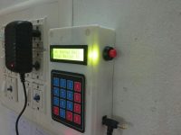
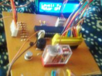
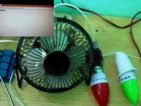
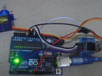
Practical Implementation of Circuit

Working
The home automation circuit is built around PIC 16F876A Microcontroller, Android App, Bluetooth module HC-05 and a 8-channel relay board. Bluetooth has a range of 10-15 meters, so that you can switch ON and OFF any electronic appliance within the range.
First install the app, it will automatically ask permission to switch on the Bluetooth of mobile phone and connect that to Bluetooth module HC 05 which located with appliance controlling part.
Here Bluetooth App operates in Control Mode and HC-05 module operates as a receiver. App Passes the commands to HC-05 RX module in order to control the home appliances.
Commands are sent to PIC 16F876A microcontroller via HC-05 Bluetooth module. PIC 16F876A microcontroller analyses the received commands from HC-05 and generates outputs at output port.
Output of PIC 16F876A microcontroller is connected load unit i.e., home appliances via driver IC 2803 and relay unit. Driver drives the respective load for the respective received command via relay as a switching unit.
Software used: MikroC compiler
Language: Embedded C
Advantages
- It is a robust and easy to use system.
- There is no need for extra training of that person who is using it.
- All the control would be in your hands by using this home automation system.
- This project can provide the facility of monitoring all the appliances with in the communication range through Bluetooth.
- Bluetooth controlled industrial devices using Android mobile is automatic versatile system.
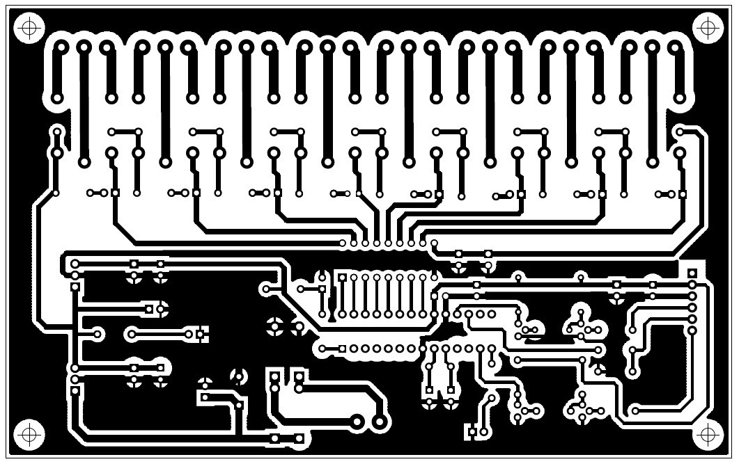
PCB
Bottom Layer
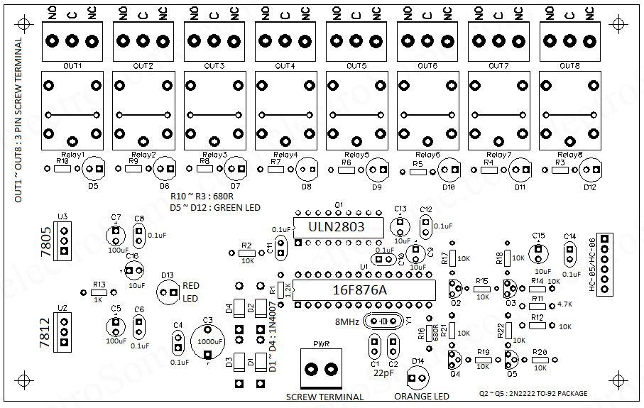
Component Layout – Top

Above project is based on PIC microcontroller, not for Arduino.
plz sir with arduino uno the compilation code gives : exit status 1
‘::main’ must return ‘int’
can you sir give me a solution? thank you .
It shouldn’t. 2 transistors are added for logic level conversion… bluetooth module is 3.3V logic while PIC is 5V…..
so adding transistor to shift 3.3V logic to 5V will give more reliable circuit.
Did you successfully implemented them??. Is there a problem with the code.
Why do I see transistor in LAYOUT diagram but in SCHEMATIC diagram you don’t draw it. Without them, does it affect the circuit.
I like your project, thanks for your post
We didn’t tested it in proteus.
Is there any way I can obtain the Proteus schematic already completed? If not I’m not able to find the parts that are labeled relay which look to me like transformers? Can I download those parts somewhere?