

Bluetooth Home Automation With CloudX
Contents
Bluetooth wireless technology has grown to become one of the widely used protocols in the field of communication today.
Although it has lower range of reach when compared to other wireless communication protocols such as WiFi and ZigBee ─with which it operates on the same frequency of 2.41 GHz; it is still very suitable for many low range applications. As a matter of fact, it has an enough bandwidth to meet most of our regular mobile and personal communication demands.
It is much convenient and easy to use; and simply transmits and receives data wirelessly between devices ─thereby taking care of the wireless side of the communication channel. It is able to communicate wirelessly in a host system through the aid of the Host Controller Interface (HCI) such as UART and USB.
Therefore, our DIY (Do It Yourself) today centers on interfacing the Bluetooth Module to realize a home automation project. Here, our HCI (Host Controller Interface) is that of UART; which is just enough to provide us the much needed Bluetooth integration for this exercise. Meanwhile, an UART option always gives optimal solutions for a Bluetooth embedded system.
Component Required
- CloudX PIC Microcontroller Development Board
- CloudX USB SoftCard
- HC-05 (ZS-040) Bluetooth Module
- Resistors
- Power Supply Unit
- Breadboard
- Jumper (Connecting) Wires
CloudX PIC Microcontroller Development Board
CloudX module is an electronics design hardware tool that allows you a much convenient and easy way of interfacing with the physical world via a simple microcontroller board. The whole platform is based on an open source physical computing. Its simplicity of an IDE (Integrated Development Environment) really makes it a perfect fit for beginners, yet retaining an enough functionality to allow the advanced end-users navigate their way through. In a nut-shell, CloudX provides for a much simplified process of handling the microcontroller −by abstracting away the normal complex details associated with it; while at the same time offering a very rich user-experience platform. It finds wide applications cutting across board:
- schools, as a great Educational tool;
- industrial and commercial products;
- and as a great utility tool in the hands of a hobbyist.

HC-05 (ZS-040) Bluetooth Module
HC-05 Bluetooth Module is a cheap and widely used for microcontroller (MCU) interfacing via the serial UART where data are transmitted in the form of packets. It is a much convenient Bluetooth SPP (Serial Port Protocol) module, making room for a transparent wireless serial connection setup. Its TX and RX pins form the basis for its communication path with the MCU.
Pin Description
It has 6 pins,
1.Key/EN:It is used to bring Bluetooth module in AT commands mode. By default this pin operates in data mode. Key/EN pin should be high to operate Bluetooth in command mode. The default baud rate of HC-05 in command mode is 38,400bps and 9600 in data mode. HC-05 module has two modes,
- Data mode: Exchange of data between devices. Baud rate is 9600bps in data mode.
- Command mode: It uses AT commands which are used to change setting of HC-05. Baud rate is 38400bps in command mode.

2. VCC: Connect 5 V or 3.3 V to this Pin.
3. GND: Ground Pin of module.
4. TXD: Connect with Microcontroller RXD pin of Microcontroller. Transmit Serial data (wirelessly received data by Bluetooth module transmitted out serially on TXD pin)
5. RXD: Connect with Microcontroller TXD pin of Microcontroller. Received data will be transmitted wirelessly by Bluetooth module.
6. State:Used to indicate the connection status of the module.
Interfacing HC-05 Bluetooth Module with CloudX
Our mobile gadgets, or even the PC’s (Personal Computers), perform a Bluetooth communication with the MCU via special applications known as Bluetooth Terminal. The apps are readily downloadable on the internet irrespective of the OS (Operating System) on which your device running on.

Mode Of Operation
The apps work such that they typically send characters through to the HC-05 Bluetooth module attached to the MCU via the host device BT (Bluetooth) protocol. Upon (the HC-05 BT module) receiving the characters, the MCU is then made to perform some defined tasks depending on what the software program must have specified. The apps are as much flexible as even some further provide an interactive GUI (Graphics User Interface) buttons that transmit certain characters at a button press. Of course, a BT interfacing is always a two mode communication whereby:
- We either send in data/command, using our host device BT, to the MCU so as to control our system of interest;
- Or we simply receive data/command from the MCU for some specific use.
Pin Connection between HC-05 Bluetooth and CloudX Board
| HC-05 Bluetooth | CloudX Board |
|---|---|
| STATE | – |
| RXD | TX |
| TXD | RX |
| GND | GND |
| VCC | 5V |
| EN | – |
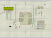
Circuit Diagram

The whole operation centers around the microcontroller module as the heartbeat of the entire project. It (MCU) can be powered on:
- either via the VIN and the GND points (ie. connecting them up to your external power-supply-unit’s +ve and –ve terminals respectively) on the board;
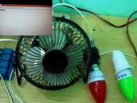
- or through your CloudX USB softcard module. As clearly illustrated in the schematic diagram above, the electric loads in the domestic automation project are adequately represented by Lamp1 and Lamp2 ─with the relay transistors connected in the current sinking mode
The MCU P1 connects to Load1 (lamp1) via a resistor , whereas its P2 connects to Load2 (lamp2) via another resistor . The BT(Bluetooth module) interfaces with MCU thus:
- The TXD-pin to MCU TX-pin via a voltage level converter; and RXD-pin to MCU RX-pin via a voltage level converter as well.
- The Vcc-pin to MCU +5V-pin; and GND-pin to MCU GND-pin.
Software Program
Code
#include <CloudX\M633.h>
#include <CloudX\Bluetooth_HC05.h>

#define Load1 pin1
#define Load2 pin2

unsigned char toggle=0;

void checkLampStatus()
{
  Bluetooth_writeText("Lamp 1: ");
  if(Load1 is ON)
  {
    Bluetooth_writeText("ON\r\n\r\n");
  }
  else
    Bluetooth_writeText("OFF\r\n\r\n");

  Bluetooth_writeText("Lamp 2: ");
  if(Load2 is ON)
  {
    Bluetooth_writeText("ON\r\n\r\n");
  }
  else
    Bluetooth_writeText("OFF\r\n\r\n");
}

void getNewCommand()
{
  char received;
  received = Bluetooth_read();
  if(received is'1' || received is'A' || received is 'a')
  {
    Load1 = ~Load1; //toggling takes place here
    Bluetooth_writeText("Lamp 1: ");
    if(Load1 is ON)
      Bluetooth_writeText("ON\r\n\r\n");
    else
      Bluetooth_writeText("OFF\r\n\r\n");
  }

  if(received is'2' || received is'B' || received is 'b')
  {
    Load2 = ~Load2; //toggling takes place
    Bluetooth_writeText("Lamp 2: ");
    if(Load2 is ON)
    {
      Bluetooth_writeText("ON\r\n\r\n");
    }
    else
      Bluetooth_writeText("OFF\r\n\r\n");
  }

  if(received is'3' || received is'C' || received is 'c')
  {
    if(toggle is 0)
    {
      Load1 = ON; Load2 = ON; toggle = 1;
    }
    else if(toggle is 1)
    {
      Load1 = OFF; Load2 = OFF; toggle = 0;
    }
    Bluetooth_writeText("Lamp 1: ");
    if(Load1 is ON)
    {
      Bluetooth_writeText("ON;\r\n\r\n");
    }
    else
      Bluetooth_writeText("OFF;\r\n\r\n");

    Bluetooth_writeText("and Lamp 2: ");
    if(Load2 is ON)
    {
      Bluetooth_writeText("ON\r\n\r\n");
    }
    else
      Bluetooth_writeText("OFF\r\n\r\n");
  }

  if(received is'4' || received is'D' || received is'd')
  checkLampStatus();
}

setup()
{
  Bluetooth_begin(9600);
  pin1Mode = OUTPUT;
  pin2Mode = OUTPUT;
  Load1 = OFF;
  Load2 = OFF;
  Bluetooth_writeText("\rWELCOME \r\n\r\n");
  Bluetooth_writeText("CloudX Lamp Initialised\r\n\r\n");

  loop()
  {
    if(Bluetooth_available()) //if serial data becomes available
    getNewCommand();
  }
}
Code Description
NB: The double slash // or the /* … */ characters in the code are simply used to mark comments; and hence the compiler does ignore them since they are not actually part of the code. Basically, the comments have all been included to aid ease of understanding as you go through the code. As can be readily seen, the operating software program is written in pure C Language, and in a very simplified manner too. As you may agree with me, everything is just self explanatory to the core.
It all begins with the Library header files necessary for the system to run, properly included.
#include <CloudX\M633.h>
#include <CloudX\Bluetooth_HC05.h>
CloudX header file must come first as it is the primary file on which the other header file (Bluetooth’s) runs. Header file holds the back-end file for any Bluetooth serial UART communication that obtains in the program.
#include <CloudX\Bluetooth_HC05.h>
The #define section is there to ensure that the usual abstract programming is rather made more relatable to you with respect to real life situation:
#define Load1 pin1
#define Load2 pin2
The terms Load1 and Load2 −which connect to the MCU’s pin P1 and P2 respectively, are made to take their (pin1, pin2) places throughout the rest of the code to further simplify things.
The getNewCommand function is there to cater for any new instruction/command coming from the end-user; while checkLampStatus function polls the on-states of the loads and reports accordingly.
The Set-up Section
This is where all the necessary configurations and initialization’s are effected:
- The serial UART communication is initialized for the Bluetooth module and configured at 9600 baud rate for a data mode of operation. Bluetooth_begin(9600);
- Then, the two MCU pins are configured as output pins to which the loads are interfaced.
pin1Mode = OUTPUT;
pin2Mode = OUTPUT; - The loads are then ensured that they remain off by default, at the start.
Load1 = OFF;
Load2 = OFF;
Subsequently, initialization messages are sent to display.
Bluetooth_writeText("\rWELCOME \r\n\r\n");
Bluetooth_writeText("CloudX Lamp Initialised\r\n\r\n");
The \r\n character inputs a new line-feed (ie. enters a new line).
The Loop Section
This section takes charge of the actual running of our system.
if(Bluetooth_available())
getNewCommand();
Download
You can download the PDF file here.

Very nice content
Hello,
What is the problem ? You are commenting the same in lot of articles ?
There is no general formula to convert analog signal to digital signal. It will vary depending on lots of factors.
Analog signal convert to digital signal formula.
Vytas Malcus Microsoft Application Developer
16620 Robinhood Dr Orland Park IL 60462