

Rain Alarm using 555 Timer
Contents
Here is a simple and interesting hobby circuit that can be made using the popular 555 timer IC. As you might already know, a 555 Timer can be easily wired as Astable, Monostable or Bistable multivibrator. This circuit can be used as rain sensor, water overflow sensor or as a water level sensor. This circuit make use the principle that normal water can conduct some amount of electricity (PURE water is not a good conductor of electricity but water seen in nature is not pure).
Components Required
- 555 Timer IC – 1
- Buzzer – 1
- BC547 Transistor – 1
- Resistor 100KΩ – 2
- Resistor 10KΩ – 1
- Resistor 1KΩ – 1
- Capacitor 10μF – 1
- Capacitor 0.01μF – 1
- Battery 9V – 1
Circuit Diagram
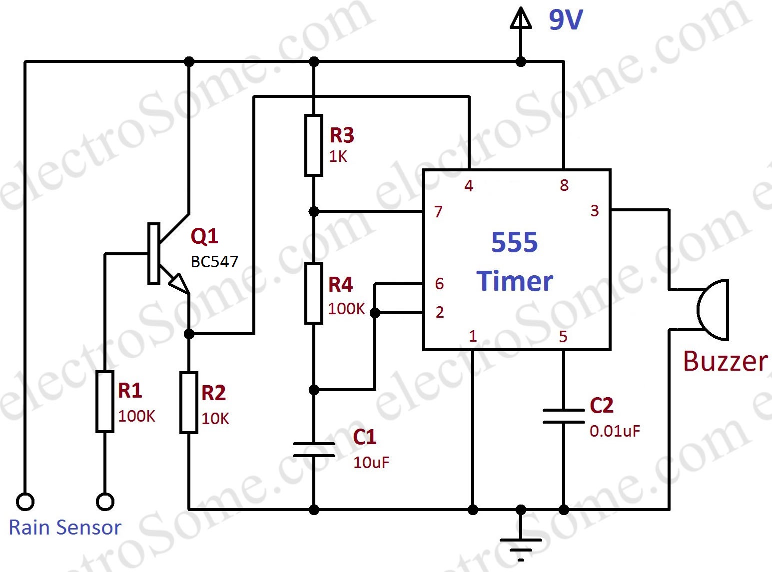
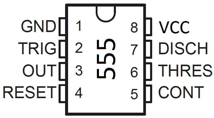
The heart of this circuit is a 555 Timer wired as an astable multivibrator. As you can see above 8th pin (VCC) of 555 is connected to positive of the supply and 1st pin (GND) is connected to the negative. A buzzer is connected to the 3ed pin (output) of 555 timer, so it will produce sound depending on the output of 555. Resistors R3, R4 and the capacitor C1 will set the time period of oscillations produced by 555. Capacitor C2 is connected to the 5th pin to avoid high frequency noises. BC547 transistor is wired as a switch whose collector is directly connected to the VCC. R2 is the emitter resistor and R1 is the base resistor of the transistor Q1.
Working
As explained above, the 555 timer is wired as an astable multivibrator. Please read the article Astable Multivibrator using 555 Timer for more explanation about it. The output frequency 555 is given by the following equation.
- Output Frequency = 1.44/((R3 + 2xR4) * C1) = 1.44/((1K + 2x100K)x10μF) = 0.72Hz
Since the buzzer is connected to the output of 555 timer, it turns ON when the output of 555 is HIGH and will be OFF when the output of 555 is LOW. So when the 555 astable operates, buzzer connected to it will produce beep sounds in 0.72Hz interval. Operation of 555 is controlled by the status of RESET pin (4th pin) which is connected the transistor BC547. 555 Timer will produce output only when RESET pin is HIGH.
The BC547 transistor Q1 is wired as a switch. Please read the article Transistor as a Switch for more explanation about it. When the transistor is ON, it will conduct current from collector to emitter, so the voltage across R2 will be HIGH. But when the transistor is OFF, it won’t conduct current from collector to emitter, thus the voltage across R2 will be LOW. When water is touched with both rain sensor terminals, current will flow into the base of the transistor via the current limiting base resistor R1. This turns the transistor ON and it conducts. This will make the RESET pin of 555 HIGH and it will start oscillations.
Note 1 : You can adjust the sensitivity of this circuit by varying the transistor base resistor R1.
Note 2 : You can change the buzzer beep frequency by changing R3, R4 or C1 as per the above equation.
Video
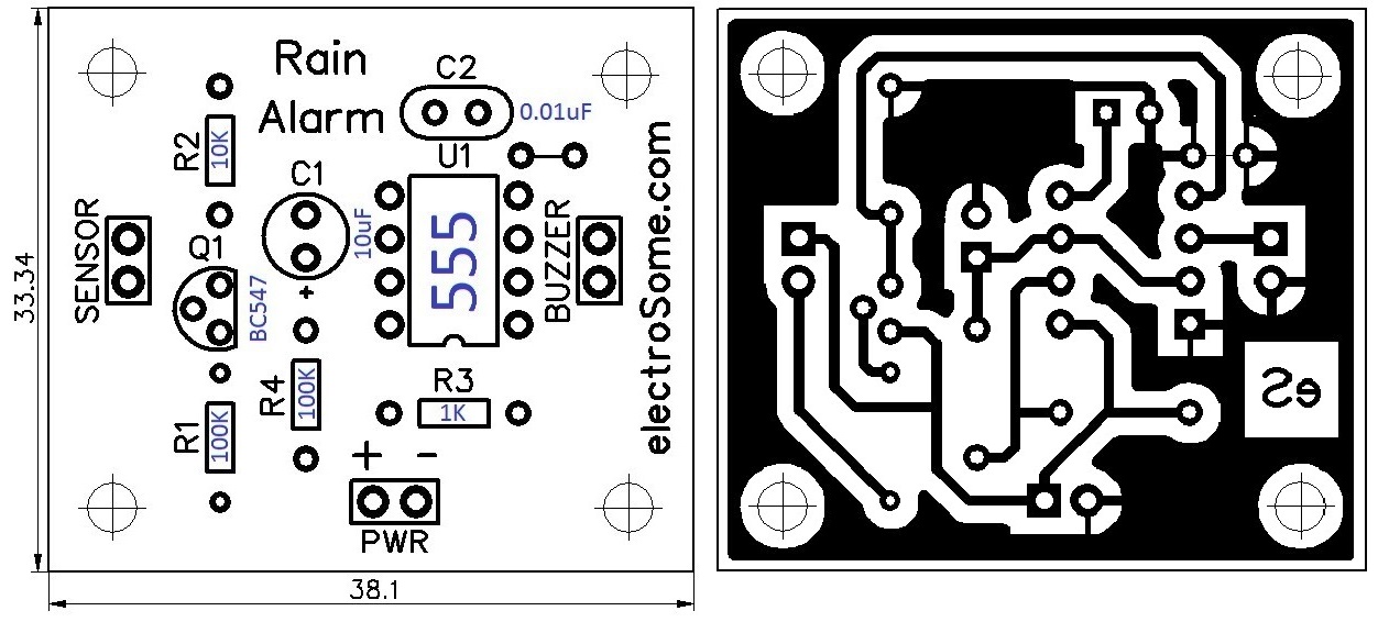
PCB
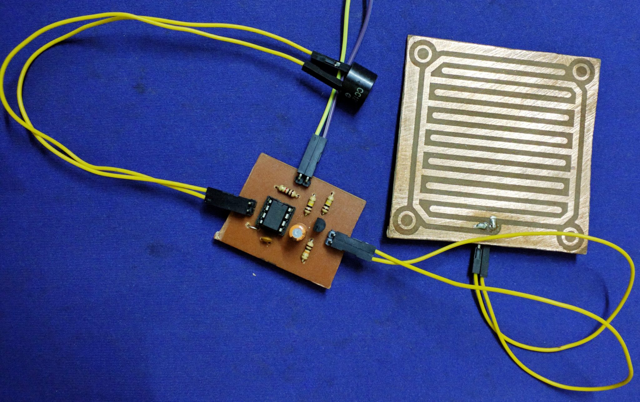
Main Board
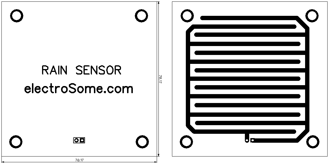
Sensor Board
Here is the one we made in our lab.
Download Here
You can download the PCB pdf files here.


Hi, very interesting your project. I am trying to reproduce it in my house, but I noticed that in the video and the images there is a transistor that is not in the list of components. Is the transistor needed? What is it?