

IoT Data Logger using Arduino and ESP8266
Contents
Today we are going to make an IoT WiFi data logger using Arduino, ESP8266 WiFi module and DHT22 temperature humidity sensor. Arduino is reading temperature and humidity sensed by DHT22 and sending it to an internet server using the ESP8266 WiFi module. Here we are using ThingSpeak as the internet server. ThingSpeak is an open source IoT application which can be used as an Internet or Intranet Server. It is providing HTTP API for data logging, location tracking, status updates etc.
Components Required
- DHT22 (Temperature and Humidity Sensor)
- ESP8266 WiFi Module
- Arduino Uno
- 16×2 LCD Display
- Breadboard
- 10KΩ potentiometer
- 1KΩ resistors
- 220Ω resistors
Circuit Diagram and Explanation
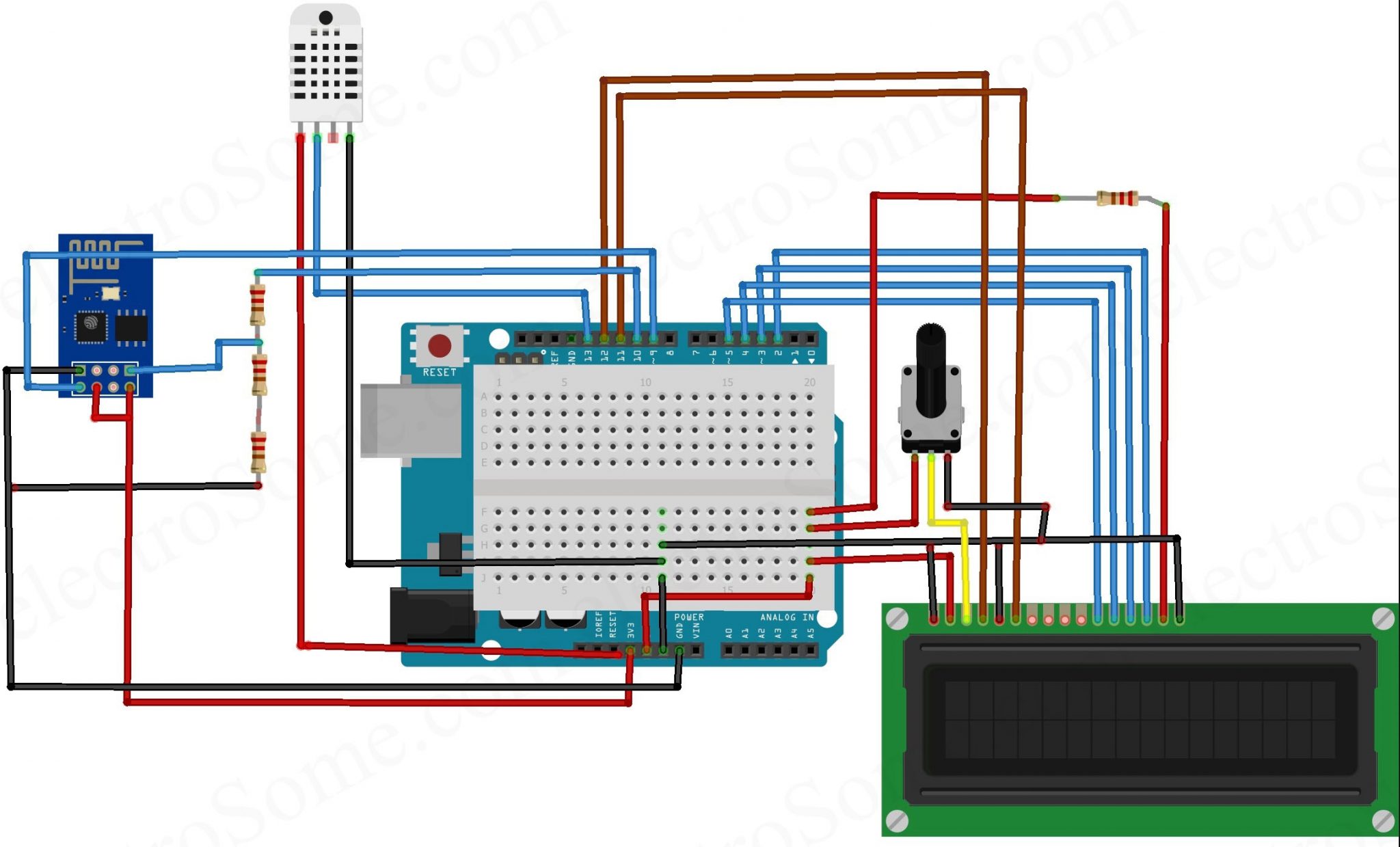
First of all, we are going to connect ESP8266 module with the Arduino. ESP8266 runs on 3.3V, so we should power it from the 3.3V output of Arduino. Connect VCC and CH_PD of ESP8266 module to the 3.3V output of Arduino and the ground of ESP8266 to the ground of Arduino. The RX pin of the ESP8266 is not 5V tolerant, so we need to reduce the 5V TX output of Arduino to 3.3V using voltage dividing resistors. Here we are using three 1KΩ resistors connected in series for that. So we will connect pin 10 (TX) of Arduino to RX of ESP8266 module via voltage dividing resistors. We can directly connect TX pin of ESP8266 to 9th (RX) of Arduino as it will detect 3.3V as logic HIGH according to TTL voltage specifications.
Then connect the DHT22 sensor to the Arduino. The first pin of the DHT22 sensor VCC power input, connect it to the 5V output pin of the Arduino. The second pin of the DHT22 is the data output pin, connect it to the pin 13 of the Arduino. The third pin is No Connection (NC) so we can leave it. Connect last pin to ground.
Now we can connect 16X2 LCD to the Arduino. The connections of LCD to Arduino are as follows.
- First pin of the LCD is the power supply ground, VSS. Connect it to the ground.
- Second pin of the LCD is the power input, VDD. Connect it to the 5V output of the Arduino.
- The third pin is VEE, which is used to adjust the contrast of the LCD display. Connect it to the variable pin of 10KΩ potentiometer. Connect the other two pins of the potentiometer to the 5V and ground. Now we can change the contrast by varying the potentiometer.
- 4th pin of LCD is RS (Register Select), connect it to pin 12 of the Arduino.
- 5th pin of LCD is R/W (Read/Write), connect it to ground as we are only going to write data to the LCD.
- 6th pin of LCD is E (Enable), connect it to pin 11 of the Arduino. This input is used to indicate a valid data or command in the following data pins.
- 7 ~ 8 pins are not using as we are using 4 bit communication mode. These pins are used only in 8 bit mode which is not commonly used as it will consume 4 more digital pins of Arduino.
- 11th pin is D4 (Data), connect it to pin 5 of Arduino.
- 12th pin is D5 (Data), connect it to pin 4 of Arduino.
- 13th pin is D6 (Data), connect it to pin 3 of Arduino.
- 14th pin is D7 (Data), connect it to pin 2 of Arduino.
- 15th pin is Anode of backlight LED, connect it to 5V through a 220Ω resistor for current limiting.
- 16th pin is Cathode of backlight LED, connect it to Ground.
ThingSpeak
ThingSpeak is an open source IoT application with HTTP API which can store and retrieve data from ‘things’ via Internet or Intranet. By using this we can easily create a network of things which can be used for applications like logging, tracking, analytics etc.
First of all,open the ThingSpeak Website and create your account.

Then go to channels and create a new channel.
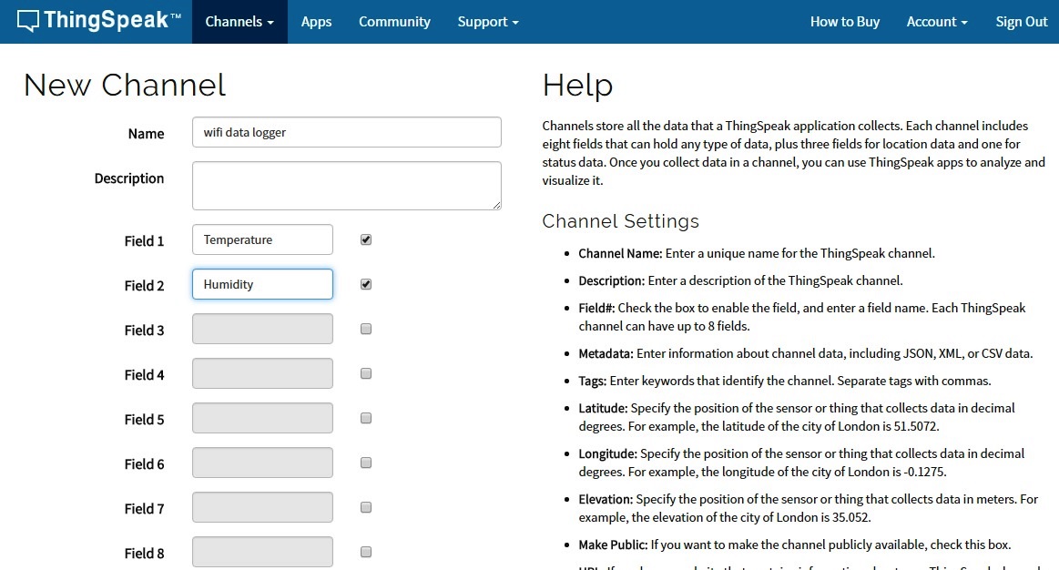
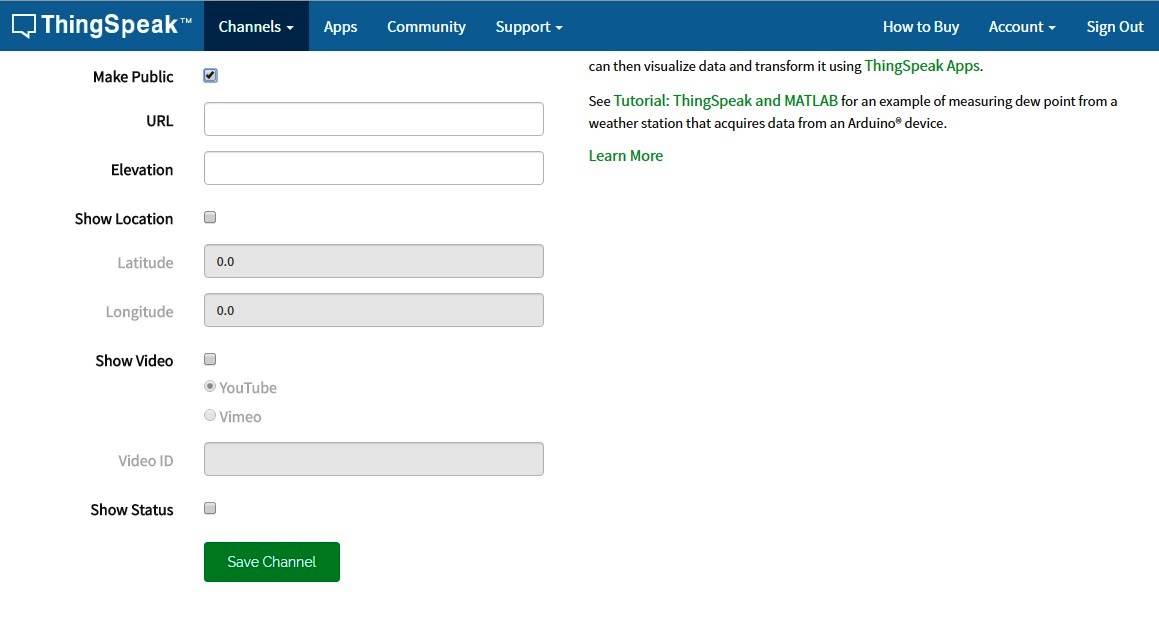
Enter the name of your channel and select two fields and name these fields. Also make the channel public by checking in the box which will be below these fields.
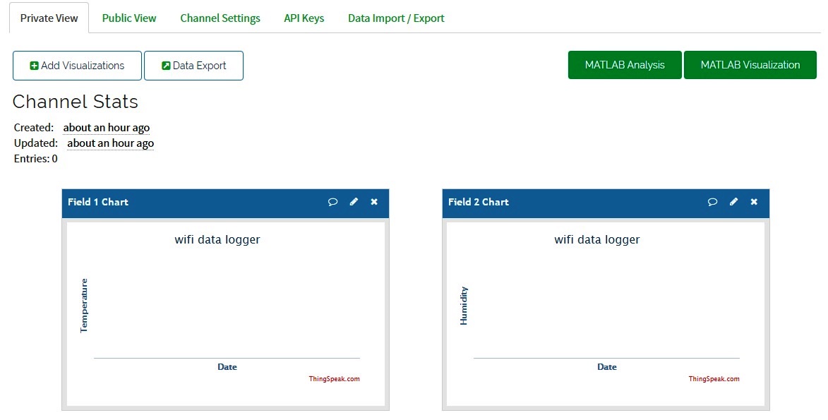
After creating, your channel will look like this.
Then goto API keys and copy your write api key. We will use this in the Arduino program.

Program and Explanation
Arduino Code
#include <SoftwareSerial.h>
#include <LiquidCrystal.h>
#include <LiquidCrystal.h>
#include <stdlib.h>
#include <DHT.h>
#define DEBUG true
#define DHTPIN 13 // DHT data pin connected to Arduino pin 2
#define DHTTYPE DHT22 // DHT 22 (or AM2302)
#define SSID "YOUR WIFI NAME" // "SSID-WiFiname"
#define PASS "YOUR WIFI PASSWORD" // "password"
#define IP "184.106.153.149" // thingspeak.com ip
String msg = "GET /update?key=M2QNKN73LG2X8TVH"; //change it with your api key like "GET /update?key=Your Api Key"
SoftwareSerial esp8266(9,10);
LiquidCrystal lcd(12,11,5,4,3,2);
DHT dht(DHTPIN, DHTTYPE); // Initialize the DHT sensor
//Variables
float temp;
int hum;
String tempC;
int error;
void setup()
{
lcd.begin(16, 2);
lcd.print("electrosome.com");
delay(100);
lcd.setCursor(0,1);
lcd.print("Connecting...");
Serial.begin(9600); //or use default 115200.
esp8266.begin(9600);
Serial.println("AT");
esp8266.println("AT");
delay(5000);
if(esp8266.find("OK"))
{
connectWiFi();
}
}
void loop()
{
lcd.clear();
//Read temperature and humidity values from DHT sensor:
start: //label
error=0;
temp = dht.readTemperature();
hum = dht.readHumidity();
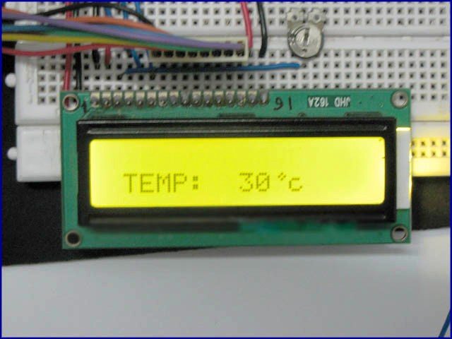
lcd.setCursor(0, 0);
lcd.print("Temp = ");
lcd.print(temp);
lcd.print(" C");
delay (100);
lcd.setCursor(0, 1); // set the cursor to column 0, line 2
lcd.print("Humi = ");
lcd.print(hum);
lcd.print(" %");
delay(1000);
char buffer[10];
// there is a useful c function called dtostrf() which will convert a float to a char array
//so it can then be printed easily. The format is: dtostrf(floatvar, StringLengthIncDecimalPoint, numVarsAfterDecimal, charbuf);
tempC = dtostrf(temp, 4, 1, buffer);
updateTemp();
//Resend if transmission is not completed
if (error==1)
{
goto start; //go to label "start"
}
delay(3600);
}
void updateTemp()
{
String cmd = "AT+CIPSTART=\"TCP\",\"";
cmd += IP;
cmd += "\",80";
Serial.println(cmd);
esp8266.println(cmd);
delay(2000);
if(esp8266.find("Error"))
{
return;
}
cmd = msg ;
cmd += "&field1="; //field 1 for temperature
cmd += tempC;
cmd += "&field2="; //field 2 for humidity
cmd += String(hum);
cmd += "\r\n";
Serial.print("AT+CIPSEND=");
esp8266.print("AT+CIPSEND=");
Serial.println(cmd.length());
esp8266.println(cmd.length());
if(esp8266.find(">"))
{
Serial.print(cmd);
esp8266.print(cmd);
}
else
{
Serial.println("AT+CIPCLOSE");
esp8266.println("AT+CIPCLOSE");
//Resend...
error=1;
}
}
boolean connectWiFi()
{
Serial.println("AT+CWMODE=1");
esp8266.println("AT+CWMODE=1");
delay(2000);
String cmd="AT+CWJAP=\"";
cmd+=SSID;
cmd+="\",\"";
cmd+=PASS;
cmd+="\"";
Serial.println(cmd);
esp8266.println(cmd);
delay(5000);
if(esp8266.find("OK"))
{
return true;
}
else
{
return false;
}
}
DHT22 Library
You need to manually add DHT library to Arduino IDE as it is not included by default. You can ignore it if you already added it. Otherwise you can do following steps for that.
- Download DHT Library from here : DHT Sensor Library.
- Open Arduino IDE.
- Go to Sketch >> Include Library >> Add .ZIP Library
- Select the downloaded ZIP file and press Open.
Code Explanation
First of all, add the libraries. The software serial library will allow you to communicate with ESP8266 via Software UART. The liquid crystal library enables us to display data in the 16×2 LCD display. DHT library is used to read temperature and humidity from the DHT22 sensor.
#include <SoftwareSerial.h>
#include <LiquidCrystal.h>
#include <stdlib.h>
#include <DHT.h>
Next is defining some constants. DHTPIN is the Arduino pin to which we are connecting the DHT22 sensor and DHTTYPE indicates the type of sensor, here it is DHT22. Then we you can define your WiFi SSID and password for connecting ESP8266 to your WiFi internet. Then enter your ThingSpeak API key which you generated above.
#define DEBUG true
#define DHTPIN 13                 // DHT data pin connected to Arduino pin 2
#define DHTTYPE DHT22             // DHT22 (or AM2302)
#define SSID "YOUR WIFI NAME"     // "SSID-WiFiname"
#define PASS "YOUR WIFI PASSWORD" // "password"
#define IP "184.106.153.149"      // thingspeak.com ip

String msg = "GET /update?key=M2QNKN73LG2X8TVH"; //change it with your api key like "GET /update?key=Your Api Key"
Then we can initialize the Software UART, LCD and DHT sensor.
SoftwareSerial esp8266(9,10);
LiquidCrystal lcd(12,11,5,4,3,2);
DHT dht(DHTPIN, DHTTYPE); // Initialize the DHT sensor
Following will display some initial data on LCD and also connect ESP8266 to your WiFi network.
  lcd.begin(16, 2);
  lcd.print("electrosome.com");
  delay(100);
  lcd.setCursor(0,1);
  lcd.print("Connecting...");
  Serial.begin(9600); //or use default 115200.
  esp8266.begin(9600);
  Serial.println("AT");
  esp8266.println("AT");

  delay(5000);

  if(esp8266.find("OK"))
  {
    connectWiFi();
  }
The following code will instruct the ESP8266 module to establish a TCP connection to the specified IP address and port number (80). Standard port of HTTP is 80.
void updateTemp()
{
  String cmd = "AT+CIPSTART=\"TCP\",\"";
  cmd += IP;
  cmd += "\",80";
  Serial.println(cmd);
  esp8266.println(cmd);
  delay(2000);
  if(esp8266.find("Error"))
  {
    return;
  }
Following code will send the current Temperature and Humidity to the ThingSpeak server via HTTP API using above established TCP connection.
  cmd = msg ;
  cmd += "&field1=";    //field 1 for temperature
  cmd += tempC;
  cmd += "&field2=";  //field 2 for humidity
  cmd += String(hum);
  cmd += "\r\n";
  Serial.print("AT+CIPSEND=");
  esp8266.print("AT+CIPSEND=");
  Serial.println(cmd.length());
  esp8266.println(cmd.length());
  if(esp8266.find(">"))
  {
    Serial.print(cmd);
    esp8266.print(cmd);
  }
The following function is used to make ESP8266 in station mode and connect it to your WiFi.
boolean connectWiFi()
{
  Serial.println("AT+CWMODE=1");
  esp8266.println("AT+CWMODE=1");
  delay(2000);
  String cmd="AT+CWJAP=\"";
  cmd+=SSID;
  cmd+="\",\"";
  cmd+=PASS;
  cmd+="\"";
  Serial.println(cmd);
  esp8266.println(cmd);
  delay(5000);
  if(esp8266.find("OK"))
  {
    return true;
  }
  else
  {
    return false;
  }
}


Serial Monitor is showing
AT+CIPSEND=56
AT+CIPCLOSE
AT+CIPSTART=”TCP”,”184.106.153.149″,80
wiring others are perfect as described.
No data is coming at Thingspeak. Plz suggest
thanks bro
Can i use MQ-135 sensor in this code?
Make sure that your ESP is wired correctly, check Reset, CH_PD/EN pins etc. Also make sure that TX is connected to RX and RX is connected to TX.
Helloo Lijo
i did this to send a data to web server for my project,but code successfully burned to Arduino problem is my esp8266 dnt ack “OK”, whats reason ,any firmware issues
kindly install DHT library.
You need to manually add DHT library to Arduino IDE as it is not included by default.
Download DHT Library from upper given link.
Open Arduino IDE.
Go to Sketch >> Include Library >> Add .ZIP Library
Select the downloaded ZIP file and press Open.
Hope its gona work for u.
Reallly amazing Project thanks for sharing ur experience great work.
using same process and same code still not working
hello friends,
i m getting this is problem pls any suggestion how to remove this problem pls any details share with me..
thankful to u ..
Arduino: 1.8.1 (Windows 7), Board: “Arduino/Genuino Uno”
C:UsersLabDocumentsArduinodthdth.ino:5:17: fatal error: DHT.h: No such file or directory
#include
^
compilation terminated.
exit status 1
Error compiling for board Arduino/Genuino Uno.
This report would have more information with
“Show verbose output during compilation”
option enabled in File -> Preferences.