

Simple Electronic Piano using 555 Timer
Contents
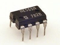
A simple electronic toy piano can be easily constructed using the popular 555 timer IC. 555 Timer can be easily wired as Astable, Monostable or Bistable multivibrator.
We all know that Sound is a Mechanical Wave as it is produced by to and fro movement of particles of the medium. Displacement of particles are in the same direction as propagation of sound waves, so sound is a Longitudinal Wave. The to and fro motion of particles in the medium creates compression (high pressure) and rarefactions (low pressure) in the medium, so sound is a Pressure Wave.
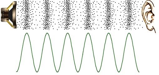
A tone is a sound which is produced by a regular vibration. So it has only one frequency even though intensity/amplitude can vary. A Loudspeaker is an electronic transducer which converts electric signals to pressure variations to make the sensation of sound. To make this diaphragm of the loudspeaker will vibrate according to the frequency and amplitude of electric signals. Audible frequency range of humans is from 20Hz to 20KHz, so we are going to generate frequencies in this range using 555 timer and feed it to the loudspeaker.
I recommend you to read the article Astable Multivibrator using 555 Timer as we are generating these frequencies by wiring 555 as an astable multivibrator.
Components Required
- 555 Timer IC – 1
- Speaker 8Ω, 0.5W – 1
- Resistor 1K – 8
- Variable Resistor 10K – 1
- Electrolytic Capacitor 10μF – 1
- Ceramic Capacitor 0.1μF – 1
- Ceramic Capacitor 0.01μF – 1
- Push Button or Micro Switch – 7
Circuit Diagram
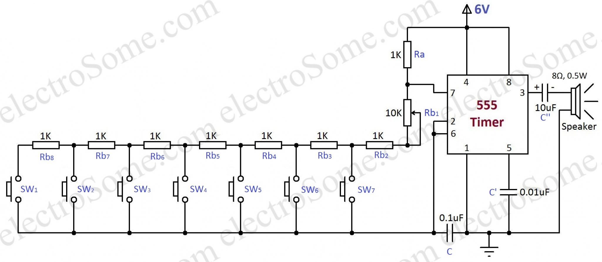
You can easily understand the working of above circuit if you know the working of Astable Multivibrator using 555. capacitor C (0.1μF) and all the resistors in the above circuit determines the frequency of oscillation of the multivibrator. Capacitor C’ (0.01μF) is connected to 5th pin to avoid high frequency noises and the capacitor C” (10μF) act as a coupling capacitor which will block dc and bypass ac signals to the loudspeaker. You can change the generated tones by varying the variable resistor Rb1 (10KΩ).
Output frequency of astable using 555 is given by, F = 1.44/((Ra + 2Rb) * C). Where Ra and C are fixed values, 1KΩ and 0.1μF respectively but the value of Rb is determined by the switch which is pressed as given below.
- SW1 – Rb1 + Rb2 + Rb3 + Rb4 + Rb5 + Rb6 + Rb7 + Rb8
- SW2 – Rb1 + Rb2 + Rb3 + Rb4 + Rb5 + Rb6 + Rb7
- SW3 – Rb1 + Rb2 + Rb3 + Rb4 + Rb5 + Rb6
- SW4 – Rb1 + Rb2 + Rb3 + Rb4 + Rb5
- SW5 – Rb1 + Rb2 + Rb3 + Rb4
- SW6 – Rb1 + Rb2 + Rb3
- SW7 – Rb1 + Rb2
So pressing each switch will generate a corresponding frequency, by which speaker will generate different tones (single frequency sound) for each switch.
Note : You can operate 555 IC from 4.5 ~ 18V power supply, but it should not exceed the power rating of loudspeaker.
Video
Please do comment if you have any doubts or concerns regarding above hobby project.
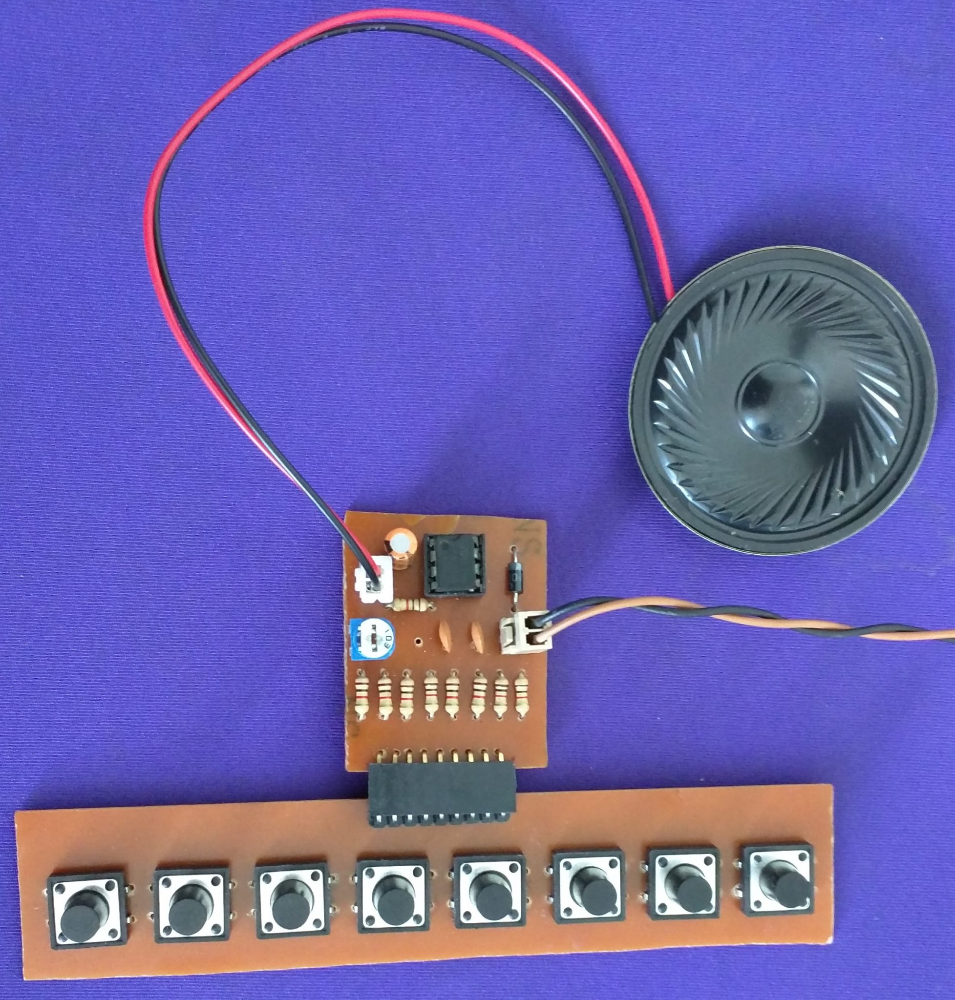
PCB

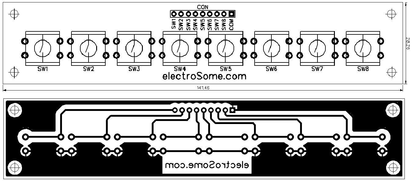
Here is the one we made in our lab.
Download Here
You can download the PCB pdf files here.


I have an idea to modify this version. Hopefully it will work! Wish me luck..
How could one add on to this idea to make it even more creative? Would appreciate any ideas!
Sir…I am facing a problem in this circuit.
Once the button is pressed, sound comeout but when it is released, sound continuously beeps. It must stop at the instant, the button is released, but it is not performing this action. What could be the error and how can we correct it ?
The problem using the same 1k resistor is that you can not tune the notes, and they are in the wrong pitch.
Better will be use potentiometers.