

Mobile Phone Detector Circuit
Contents
This is a very interesting hobby project which can detect active mobile phone or GSM communication in its proximity. Active mobile phone means there is some live communication is going on like calls, sms sending or receiving etc. This circuit can be used to prevent unauthorized use of mobile phones in examination halls, conference rooms etc. As you already know, today’s mobile phones (2G, 2.5G, 3G, 4G, LTE) are operating in electromagnetic signals ranges from 700MHz to 3500MHz. Each countries will have its own rules and regulations for frequency bands. So in this project we will be detecting electromagnetic radiations in this frequency bands and it will give you a detection range about 2 meters.
Components Required
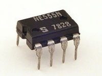
- 555 Timer IC
- CA3130 Op-Amp
- BC548 Transistor
- Buzzer
- 2x 1KΩ Resistors
- 2x 2.2MΩ Resistors
- 15KΩ Resistor
- 2x 100KΩ Resistors
- 47pF Capacitor
- 22μF Capacitor
- 0.1μF Capacitor
- 22pF Capacitor
- 0.01μF Capacitor
- 4.7μF Capacitor
- ON-OFF Switch
- 2x LEDs
- 9V Battery
- Battery Connector
- PCB
Circuit Diagram
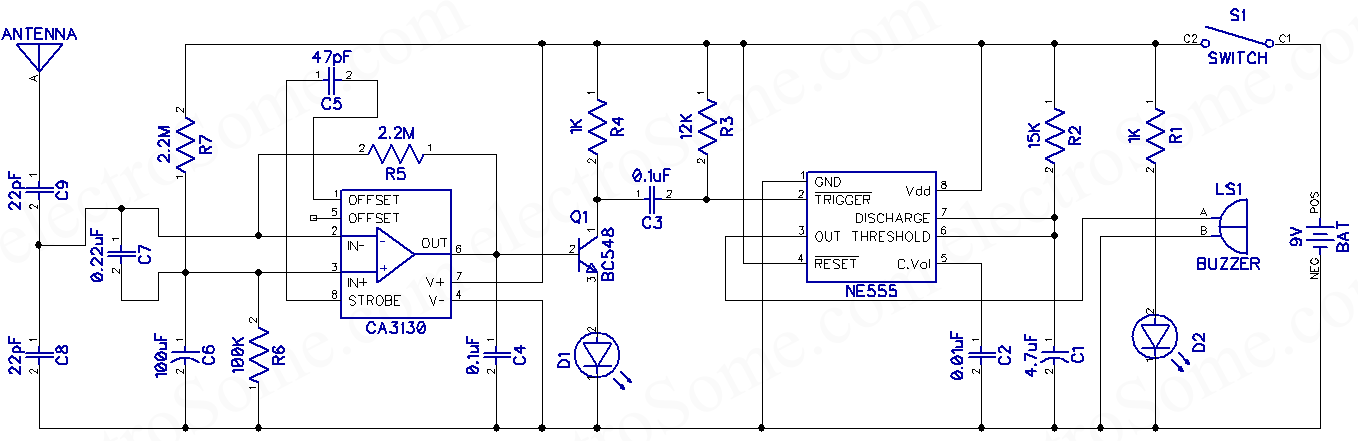
The circuit can be basically divided into two parts,
- RF Signal Detector
- Sound Generator
RF Signal Detector
The first half of the circuit makes RF signal detecting section. Capacitor C7 (0.22μF) is the main component which will sense high frequency RF signals. CA3130 opamp is wired as an inverting amplifier with high gain. It provides very high input impedance and high speed performance to amplify RF signals detected by the capacitor C7. You can see that one terminal of the capacitor C7 is biased with two resistors R6 and R7. Capacitor C6 (100μF) will prevent any fluctuations in the bias voltage. Capacitors C9 and C8 (22pF) are used to filter input signals. Thus in normal conditions the opamp will be in balanced state.
So when high frequency mobile signals are present in the vicinity of this circuit, the capacitor C7 will get energized and distorts the balance of the opamp. This operates the Q1 (BC548) transistor wired as a switch. Thus the LED D1 is operated and signals are coupled to the next section for generating sound indication.
Sound Generator
Sound generator is composed of a 555 Timer wired as monostable multivibrator and a buzzer. Output signals from RF Signal Detection section will trigger the 555 timer. Time period of each tone can be adjusted by varying the capacitor C1 and resistor R2.
Working
I suggest you to watch the following video to understand how this circuit operates. When the circuit is switched on, LED D2 will indicate that it is ON. Now you can place a mobile near this circuit and try making a call or sending an SMS. You can see that the buzzer is producing sound and LED D1 is indicating detection of signals.
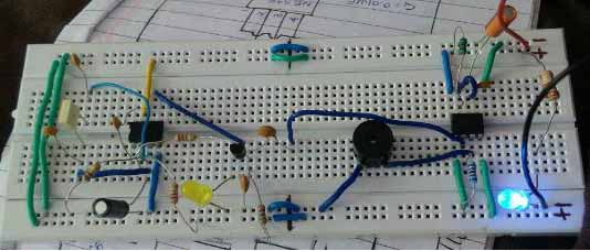
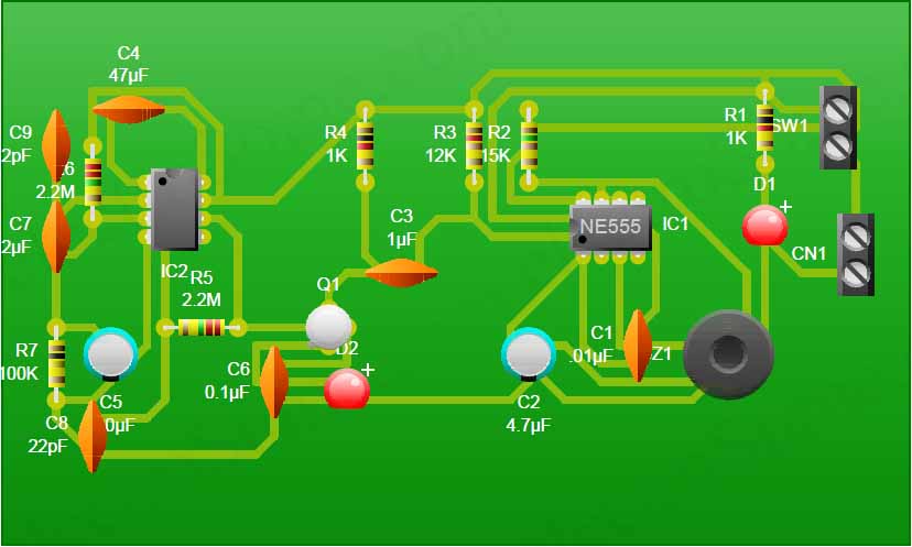
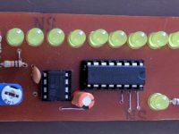
Making
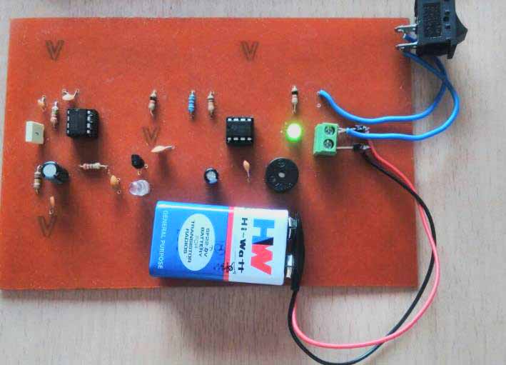
Note : You can use a 5-inch long antenna to increase detection range of this circuit.
Video
Download Here
You can download PCB PDF files here.


C4, C6, C1, C3 seem to have different capacitance values in the different pictures. Are the values not that critical, or is the first schematic the correct one (as opposed to the image that is in color halfway down the page.