

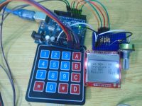
Digital Alarm Clock using PIC Microcontroller and DS3234 RTC
Contents
Here is a digital alarm clock made using PIC 18F4520 Microcontroller and DS3234 RTC (Real Time Clock). This project is for educational purposes or can be used as a reference for integrating DS3234 RTC. DS3234 is a very accurate RTC IC with integrated on chip temperature compensated crystal oscillator. It can be integrated with a microcontroller using SPI bus. This project is developed using MPLAB XC8 compiler.
Components Required
- PIC 18F4520 Microcontroller
- DS3234 RTC
- 20MHz Crystal
- 4×3 Keypad
- 16×2 LCD
- 10KΩ preset
- 5V buzzer
- LED
- BC547 Transistor
- Capacitor 22pF – 2
- Resistor 680Ω
- Resistor 10KΩ – 5
Circuit Diagram

I hope that you can easily understand the circuit diagram. The circuit is powered using a 5V power supply. 20MHz crystal is connected to PIC Microcontroller to provide necessary clock for the operation. MCLR pin is directly tied to VDD. DS3234 RTC is connected to the PIC microcontroller via SPI bus and interrupt output of RTC IC is connected to RB0 of the PIC microcontroller to trigger alarm. 4X3 keypad is connected to RD0 – RD6 pin of the PIC microcontroller. RD7 pin of PIC microcontroller, which is configured as an output is connected to a buzzer and an LED via a BC547 NPN transistor wired as a switch.
Note 1 : VBAT of the RTC IC is not connected in the above circuit diagram. It is highly recommenced to connect it to a 3V button cell or coin cell battery to keep the time in case of main power failure.
Note 2 : It is highly recommended to add 4 schottky diodes to 4 outputs to the keypad (RD3 ~ RD6) to avoid possible damage to the microcontroller if two keys are pressed simultaneously. For example, in the above circuit if we accidentally press keys 1 and key 4 at the same time, it will short RD3 and RD4 pins of the microcontroller. It will cause higher current consumption when either of the pin is held high during keypad scanning. Thank you “Tim Nicholson” for suggesting this in the comments section.
MPLAB XC8 Code
Program is little lengthy, click here to view the code.
/*
* File: newmain.c
* Author: Ligo George
*
* Created on March 4, 2016, 7:06 AM
*/
// PIC18F4520 Configuration Bit Settings
// 'C' source line config statements
// CONFIG1H
#pragma config OSC = HS // Oscillator Selection bits (HS oscillator)
#pragma config FCMEN = OFF // Fail-Safe Clock Monitor Enable bit (Fail-Safe Clock Monitor disabled)
#pragma config IESO = OFF // Internal/External Oscillator Switchover bit (Oscillator Switchover mode disabled)
// CONFIG2L
#pragma config PWRT = OFF // Power-up Timer Enable bit (PWRT disabled)
#pragma config BOREN = SBORDIS // Brown-out Reset Enable bits (Brown-out Reset enabled in hardware only (SBOREN is disabled))
#pragma config BORV = 3 // Brown Out Reset Voltage bits (Minimum setting)
// CONFIG2H
#pragma config WDT = OFF // Watchdog Timer Enable bit (WDT disabled (control is placed on the SWDTEN bit))
#pragma config WDTPS = 32768 // Watchdog Timer Postscale Select bits (1:32768)
// CONFIG3H
#pragma config CCP2MX = PORTC // CCP2 MUX bit (CCP2 input/output is multiplexed with RC1)
#pragma config PBADEN = OFF // PORTB A/D Enable bit (PORTB<4:0> pins are configured as digital I/O on Reset)
#pragma config LPT1OSC = OFF // Low-Power Timer1 Oscillator Enable bit (Timer1 configured for higher power operation)
#pragma config MCLRE = ON // MCLR Pin Enable bit (MCLR pin enabled; RE3 input pin disabled)
// CONFIG4L
#pragma config STVREN = OFF // Stack Full/Underflow Reset Enable bit (Stack full/underflow will not cause Reset)
#pragma config LVP = OFF // Single-Supply ICSP Enable bit (Single-Supply ICSP disabled)
#pragma config XINST = OFF // Extended Instruction Set Enable bit (Instruction set extension and Indexed Addressing mode disabled (Legacy mode))
// CONFIG5L
#pragma config CP0 = OFF // Code Protection bit (Block 0 (000800-001FFFh) not code-protected)
#pragma config CP1 = OFF // Code Protection bit (Block 1 (002000-003FFFh) not code-protected)
#pragma config CP2 = OFF // Code Protection bit (Block 2 (004000-005FFFh) not code-protected)
#pragma config CP3 = OFF // Code Protection bit (Block 3 (006000-007FFFh) not code-protected)
// CONFIG5H
#pragma config CPB = OFF // Boot Block Code Protection bit (Boot block (000000-0007FFh) not code-protected)
#pragma config CPD = OFF // Data EEPROM Code Protection bit (Data EEPROM not code-protected)
// CONFIG6L
#pragma config WRT0 = OFF // Write Protection bit (Block 0 (000800-001FFFh) not write-protected)
#pragma config WRT1 = OFF // Write Protection bit (Block 1 (002000-003FFFh) not write-protected)
#pragma config WRT2 = OFF // Write Protection bit (Block 2 (004000-005FFFh) not write-protected)
#pragma config WRT3 = OFF // Write Protection bit (Block 3 (006000-007FFFh) not write-protected)
// CONFIG6H
#pragma config WRTC = OFF // Configuration Register Write Protection bit (Configuration registers (300000-3000FFh) not write-protected)
#pragma config WRTB = OFF // Boot Block Write Protection bit (Boot block (000000-0007FFh) not write-protected)
#pragma config WRTD = OFF // Data EEPROM Write Protection bit (Data EEPROM not write-protected)
// CONFIG7L
#pragma config EBTR0 = OFF // Table Read Protection bit (Block 0 (000800-001FFFh) not protected from table reads executed in other blocks)
#pragma config EBTR1 = OFF // Table Read Protection bit (Block 1 (002000-003FFFh) not protected from table reads executed in other blocks)
#pragma config EBTR2 = OFF // Table Read Protection bit (Block 2 (004000-005FFFh) not protected from table reads executed in other blocks)
#pragma config EBTR3 = OFF // Table Read Protection bit (Block 3 (006000-007FFFh) not protected from table reads executed in other blocks)
// CONFIG7H
#pragma config EBTRB = OFF // Boot Block Table Read Protection bit (Boot block (000000-0007FFh) not protected from table reads executed in other blocks)
#include <xc.h>
#include <pic18f4520.h>
#define _XTAL_FREQ 20000000 //Crystal Oscillator Frequency
//LCD Connections Start
#define RS LATBbits.LATB2
#define EN LATBbits.LATB3
#define D4 LATBbits.LATB4
#define D5 LATBbits.LATB5
#define D6 LATBbits.LATB6
#define D7 LATBbits.LATB7
//LCD Connections End
#define ALMtd 200 //Alarm & Repeat Time Setting
short bz; //Alarm Buzzer Times
void Lcd_Port(char a) //Send Data to LCD Port
{
if(a & 1)
D4 = 1;
else
D4 = 0;
if(a & 2)
D5 = 1;
else
D5 = 0;
if(a & 4)
D6 = 1;
else
D6 = 0;
if(a & 8)
D7 = 1;
else
D7 = 0;
}
void Lcd_Cmd(char a) //Send Command to LCD
{
RS = 0; // => RS = 0
Lcd_Port(a);
EN = 1; // => E = 1
__delay_ms(1);
EN = 0; // => E = 0
}
void Lcd_Clear() //Clear LCD Display
{
Lcd_Cmd(0);
Lcd_Cmd(1);
__delay_ms(1);
}
void Lcd_Cursor_ON() //Turns ON LCD Cursor
{
Lcd_Cmd(0);
Lcd_Cmd(0xF);
__delay_ms(1);
}
void Lcd_Cursor_OFF() // Turns OFF LCD Cursor
{
Lcd_Cmd(0);
Lcd_Cmd(0xC);
__delay_ms(1);
}
void Lcd_Set_Cursor(char a, char b) //Set LCD Cursor Location
{
char temp,z,y;
if(a == 1)
{
temp = 0x80 + b - 1;
z = temp>>4;
y = temp & 0x0F;
Lcd_Cmd(z);
Lcd_Cmd(y);
}
else if(a == 2)
{
temp = 0xC0 + b - 1;
z = temp>>4;
y = temp & 0x0F;
Lcd_Cmd(z);
Lcd_Cmd(y);
}
}
void Lcd_Init() //Initialize LCD
{
Lcd_Port(0x00);
__delay_ms(20);
Lcd_Cmd(0x03);
__delay_ms(5);
Lcd_Cmd(0x03);
__delay_ms(11);
Lcd_Cmd(0x03);
/////////////////////////////////////////////////////
Lcd_Cmd(0x02);
Lcd_Cmd(0x02);
Lcd_Cmd(0x08);
Lcd_Cmd(0x00);
Lcd_Cmd(0x0C);
Lcd_Cmd(0x00);
Lcd_Cmd(0x06);
}
void Lcd_Write_Char(char a) //Write a Character to LCD Display
{
char temp,y;
temp = a&0x0F;
y = a&0xF0;
RS = 1; // => RS = 1
Lcd_Port(y>>4); //Data transfer
EN = 1;
__delay_us(40);
EN = 0;
Lcd_Port(temp);
EN = 1;
__delay_us(40);
EN = 0;
__delay_ms(1);
}
void Lcd_Write_String(char *a) //Write String to LCD Disply
{
int i;
for(i=0;a[i]!='\0';i++)
Lcd_Write_Char(a[i]);
}
void spiMasterInit( void ) //Initialize SPI as Master
{
SSPSTAT = 0x00; // SMP=0(slave mode),CKE=0(transmission on Idle to active clock state), all other bits 0
SSPCON1 = 0x22; // SSPEN = 1 (enable serial port), SSPM[3-0] = 0b0010 (master mode, clcok=FOSC/64), all other bits are zero
TRISCbits.RC3 = 0;
TRISCbits.RC5 = 0;
}
void writeSPI(char dat) //Write data to SPI bus
{
SSPBUF = dat;
__delay_ms(1);
}
short spiDataReady() //Check whether the data is ready to read
{
if(SSPSTATbits.BF)
return 1;
else
return 0;
}
char readSPI() //REad the received data
{
while ( !SSPSTATbits.BF ); // wait until the all bits receive
return(SSPBUF); // read the received data from the buffer
}
unsigned short readDS3234(unsigned short address) //Read data from RTC from the given address
{
PORTBbits.RB1 = 0; //Enable Slave SPI RTC
__delay_us(10);
writeSPI(0x00 + address);
writeSPI(0x00); //Write any dummy data to provide SPI clock to read data
__delay_us(10);
PORTBbits.RB1 = 1; //Disable Slave SPI RTC
return(readSPI());
}
void writeDS3234(unsigned short address, unsigned short data)// Write data to RTC to the given address
{
PORTBbits.RB1 = 0; //Enable Slave SPI RTC
__delay_us(10);
writeSPI(0x80 + address);
writeSPI(data);
__delay_us(10);
PORTBbits.RB1 = 1; //Disable Slave SPI RTC
}
unsigned char BCD2UpperCh(unsigned short bcd) //Converter Upper BCD digit to Character
{
return ((bcd >> 4) + '0');
}
unsigned char BCD2LowerCh(unsigned short bcd) //Convert Lower BCD digit to Character
{
return ((bcd & 0x0F) + '0');
}
unsigned short Binary2BCD(unsigned short a) // Convert Binary number to BCD
{
int t1, t2;
t1 = a%10;
t1 = t1 & 0x0F;
a = a/10;
t2 = a%10;
t2 = 0x0F & t2;
t2 = t2 << 4;
t2 = 0xF0 & t2;
t1 = t1 | t2;
return t1;
}
unsigned short BCD2Binary(unsigned short a) // Convert BCD to Binary
{
int r,t;
t = a & 0x0F;
r = t;
a = 0xF0 & a;
t = a >> 4;
t = 0x0F & t;
r = t*10 + r;
return r;
}
short readKeypad() //Scan the Keypad
{
LATDbits.LATD3 = 1;
__delay_us(10);
if(PORTDbits.RD0 == 1)
{
while(PORTDbits.RD0 == 1);
return 3;
}
else if(PORTDbits.RD1 == 1)
{
while(PORTDbits.RD1 == 1);
return 2;
}
else if(PORTDbits.RD2 == 1)
{
while(PORTDbits.RD2 == 1);
return 1;
}
LATDbits.LATD3 = 0;
LATDbits.LATD4 = 1;
__delay_us(10);
if(PORTDbits.RD0 == 1)
{
while(PORTDbits.RD0 == 1);
return 6;
}
else if(PORTDbits.RD1 == 1)
{
while(PORTDbits.RD1 == 1);
return 5;
}
else if(PORTDbits.RD2 == 1)
{
while(PORTDbits.RD2 == 1);
return 4;
}
LATDbits.LATD4 = 0;
LATDbits.LATD5 = 1;
__delay_us(10);
if(PORTDbits.RD0 == 1)
{
while(PORTDbits.RD0 == 1);
return 9;
}
else if(PORTDbits.RD1 == 1)
{
while(PORTDbits.RD1 == 1);
return 8;
}
else if(PORTDbits.RD2 == 1)
{
while(PORTDbits.RD2 == 1);
return 7;
}
LATDbits.LATD5 = 0;
LATDbits.LATD6 = 1;
__delay_us(10);
if(PORTDbits.RD0 == 1)
{
while(PORTDbits.RD0 == 1);
return 12;
}
else if(PORTDbits.RD1 == 1)
{
while(PORTDbits.RD1 == 1);
return 11;
}
else if(PORTDbits.RD2 == 1)
{
while(PORTDbits.RD2 == 1);
return 10;
}
LATDbits.LATD6 = 0;
return 0;
}
char decodeCharacter(short a) //Convert keypad value to character
{
switch(a)
{
case 11 : return '0';
case 1 : return '1';
case 2 : return '2';
case 3 : return '3';
case 4 : return '4';
case 5 : return '5';
case 6 : return '6';
case 7 : return '7';
case 8 : return '8';
case 9 : return '9';
}
}
__interrupt() void alarm(void) //interrupt function called when alarm triggers
{
if(INT0IF == 1)
{
bz = 3;
writeDS3234(0x0F,0xC8);
INT0IF = 0;
}
}
void main(void)
{
unsigned short second, minute, hour, hr, day, dday, month, year, ap, m;
unsigned short aSecond,aMinute,aHour,aHr,aAP,aTM1,aTM2;
short kp,mt,temp;
char t;
char time[] = "00:00:00 PM";
char aTime[] = "00:00:00 ";
char date[] = "00-00-00 ";
TRISD = 0x07; //First 3 pins of PORTD are input
LATD = 0x00;
TRISB = 0x01;// First pin ofPORTB as input
GIE = 1; //Global Interrupt Enable
PEIE = 1;//Peripheral Interrupt Enable
INT0IF = 0;//Clear INT0 interrupt flag
INTEDG0 = 0;// Set high to low transition as INT0 interrupt
INT0IE = 1; //Enable INT0 interrupt
PORTBbits.RB1 = 1;//Disable slave
m = 0;
mt = 0;
bz = 0;
spiMasterInit();
Lcd_Init();
Lcd_Clear();
aTM1 = 0;
aTM2 = 0;
while(1)
{
second = readDS3234(0);
minute = readDS3234(1);
hour = readDS3234(2);
hr = hour & 0b00011111;
ap = hour & 0b00100000;
dday = readDS3234(3);
day = readDS3234(4);
month = readDS3234(5);
year = readDS3234(6);
time[0] = BCD2UpperCh(hr);
time[1] = BCD2LowerCh(hr);
time[3] = BCD2UpperCh(minute);
time[4] = BCD2LowerCh(minute);
time[6] = BCD2UpperCh(second);
time[7] = BCD2LowerCh(second);
if(bz)
{
if(aTM1 < ALMtd)
{
LATDbits.LATD7 = 1;//Turn on alarm
aTM1++;
}
else if(aTM1 >= ALMtd && aTM2 < ALMtd)
{
LATDbits.LATD7 = 0;//Turn off alarm
aTM2++;
}
else
{
aTM1 = 0;
aTM2 = 0;
bz--;
}
}
else
LATDbits.LATD7 = 0;//Turn off alarm
if(ap)
{
time[9] = 'P';
time[10] = 'M';
}
else
{
time[9] = 'A';
time[10] = 'M';
}
date[0] = BCD2UpperCh(day); //10s digit of Date, BCD to Character
date[1] = BCD2LowerCh(day); //1s digit of Date, BCD to Character
date[3] = BCD2UpperCh(month);
date[4] = BCD2LowerCh(month);
date[6] = BCD2UpperCh(year);
date[7] = BCD2LowerCh(year);
kp = readKeypad(); //Read Keypad
t = 0;
if(kp == 10) //If * pressed
{
m++;
mt = 0;
if(m > 3)
m = 0;
}
else if((kp > 0 && kp < 10) || kp == 11) //If valid key is pressed
{
if(m)
{
t = decodeCharacter(kp); //Convert Keypad to Character
mt++;
}
}
else if(kp == 12) //Exit or Alarm OFF if # pressed
{
m = 0; //Exit settings
bz = 0; //Alarm OFF
}
if(m == 0)
{
Lcd_Set_Cursor(1,1);
Lcd_Write_String("Time: ");
Lcd_Write_String(time);
Lcd_Set_Cursor(2,1);
Lcd_Write_String("Date: ");
Lcd_Write_String(date);
}
else if(m == 1) //Alarm Settings
{
aSecond = readDS3234(0x07);
aMinute = readDS3234(0x08);
aHour = readDS3234(0x09);
aHr = aHour & 0b00011111;
aAP = aHour & 0b00100000;
aTime[0] = BCD2UpperCh(aHr);
aTime[1] = BCD2LowerCh(aHr);
aTime[3] = BCD2UpperCh(aMinute);
aTime[4] = BCD2LowerCh(aMinute);
aTime[6] = BCD2UpperCh(aSecond);
aTime[7] = BCD2LowerCh(aSecond);
if(aAP)
{
aTime[9] = 'P';
aTime[10] = 'M';
}
else
{
aTime[9] = 'A';
aTime[10] = 'M';
}
Lcd_Set_Cursor(1,1);
Lcd_Write_String("Set Alarm ");
Lcd_Set_Cursor(2,1);
Lcd_Write_String("Time: ");
Lcd_Write_String(aTime);
if(mt && t && kp)
{
if(mt == 1 && t < '2')
{
aHour = BCD2Binary(aHr);
temp = aHour % 10;
aHour = (t - 48)*10 + temp;
aHour = Binary2BCD(aHour);
aHour = aHour | 0x40;
writeDS3234(0x09, aHour);
}
else if(mt == 2)
{
aHour = BCD2Binary(aHr);
aHour = aHour/10;
aHour = aHour*10 + (t - 48);
if(aHour < 13 && aHour > 0)
{
aHour = Binary2BCD(aHour);
aHour = aHour | 0x40;
writeDS3234(0x09, aHour);
}
}
else if(mt == 3 && t < '6')
{
aMinute = BCD2Binary(aMinute);
temp = aMinute % 10;
aMinute = (t - 48)*10 + temp;
aMinute = Binary2BCD(aMinute);
writeDS3234(0x08, aMinute);
}
else if(mt == 4)
{
aMinute = BCD2Binary(aMinute);
aMinute = aMinute/10;
aMinute = aMinute*10 + (t - 48);
if(aMinute < 60)
{
aMinute = Binary2BCD(aMinute);
writeDS3234(0x08, aMinute);
}
}
else if(mt == 5)
{
aSecond = 0;
writeDS3234(0x07, aSecond);
}
else if(mt == 6)
{
aHour = readDS3234(0x09);
if(aAP)
{
aHour = aHour & 0b11011111;
}
else
{
aHour = aHour | 0b00100000;
}
writeDS3234(0x09,aHour);
mt = 0;
}
writeDS3234(0x0A,0x80);
writeDS3234(0x0F,0xC8);
writeDS3234(0x0E,0x1D);
}
}
else if(m == 2) //Time Settings
{
if(mt && t && kp)
{
if(mt == 1 && t < '2')
{
hour = BCD2Binary(hr);
temp = hour % 10;
hour = (t - 48)*10 + temp;
hour = Binary2BCD(hour);
hour = hour | 0x40;
writeDS3234(2, hour);
}
else if(mt == 2)
{
hour = BCD2Binary(hr);
hour = hour/10;
hour = hour*10 + (t - 48);
if(hour < 13 && hour > 0)
{
hour = Binary2BCD(hour);
hour = hour | 0x40;
writeDS3234(2, hour);
}
}
else if(mt == 3 && t < '6')
{
minute = BCD2Binary(minute);
temp = minute % 10;
minute = (t - 48)*10 + temp;
minute = Binary2BCD(minute);
writeDS3234(1, minute);
}
else if(mt == 4)
{
minute = BCD2Binary(minute);
minute = minute/10;
minute = minute*10 + (t - 48);
if(minute < 60)
{
minute = Binary2BCD(minute);
writeDS3234(1, minute);
}
}
else if(mt == 5)
{
second = 0;
writeDS3234(0, second);
}
else if(mt == 6)
{
hour = readDS3234(2);
if(ap)
{
hour = hour & 0b11011111;
writeDS3234(2,hour);
}
else
{
hour = hour | 0b00100000;
writeDS3234(2,hour);
}
mt = 0;
}
}
Lcd_Set_Cursor(1,1);
Lcd_Write_String("Set Time ");
Lcd_Set_Cursor(2,1);
Lcd_Write_String("Time: ");
Lcd_Write_String(time);
}
else if(m == 3) //Date Settings
{
if(mt && t && kp)
{
if(mt == 1 && t < '4')
{
day = BCD2Binary(day);
temp = day % 10;
day = (t - 48)*10 + temp;
day = Binary2BCD(day);
writeDS3234(4, day);
}
else if(mt == 2)
{
day = BCD2Binary(day);
day = day/10;
day = day*10 + (t - 48);
if(day < 32 && day > 0)
{
day = Binary2BCD(day);
writeDS3234(4, day);
}
}
else if(mt == 3 && t < '2')
{
month = BCD2Binary(month);
temp = month % 10;
month = (t - 48)*10 + temp;
month = Binary2BCD(month);
writeDS3234(5, month);
}
else if(mt == 4)
{
month = BCD2Binary(month);
month = month/10;
month = month*10 + (t - 48);
if(month < 13 && month > 0)
{
month = Binary2BCD(month);
writeDS3234(5, month);
}
}
else if(mt == 5)
{
year = BCD2Binary(year);
temp = year % 10;
year = (t - 48)*10 + temp;
year = Binary2BCD(year);
writeDS3234(6, year);
}
else if(mt == 6)
{
year = BCD2Binary(year);
year = year/10;
year = year*10 + (t - 48);
year = Binary2BCD(year);
writeDS3234(6, year);
}
}
Lcd_Set_Cursor(1,1);
Lcd_Write_String("Set Date ");
Lcd_Set_Cursor(2,1);
Lcd_Write_String("Date: ");
Lcd_Write_String(date);
}
}
}
I hope that you can easily understand the code as it is well commented. Please not below points before going through the program. If you still have doubts, please feel free to comment below.
- #pragma directive is used to set configuration bits of PIC microcontroller.
- Lcd_Port() function writes 4-bit data to LCD data pins.
- Lcd_Cmd() function is used to send a command to LCD.
- Lcd_Clear() function clears the LCD.
- Lcd_Cursor_ON() function turns the cursor ON in the display.
- Lcd_Cursor_OFF() function turns the cursor OFF in the display.
- Lcd_Set_Cursor() function sets the current location of the cursor.
- Lcd_Init() function initializes the LCD.
- Lcd_Write_Char() function writes a character to the current cursor location.
- Lcd_Write_String() function writes a string, starting from current cursor location.
- spiMasterInit() function initializes the PIC’s SPI module as master.
- writeSPI() function writes one byte of data to SPI bus.
- spiDataReady() function checks whether data is ready to be read in the buffer.
- readSPI() function reads received data from the SPI buffer.
- readDS3234() function reads data from the specified address of DS3234 RTC IC.
- writeDS3234() function writes data to the specified address of DS3234 RTC IC.
All the contents in time/date registers in DS3234 are in Binary Coded Decimal (BCD) format. So we need to convert BCD to corresponding numerical characters for displaying in the LCD display. We also need to convert BCD to normal format (binary or decimal) and vice versa for all calculations like increment or decrement time/date.
- BCD2UpperCh() will return the corresponding upper character of the BCD value. For eg. if the hour is “10”, the BCD value will be 0x10 or 16. This function will return character “1”.
- BCD2LowerCh() will return the corresponding lower character of the BCD value. For eg. if the hour is “10”, the BCD value will be 0x10 or 16. This function will return character “0”.
- BCD2Binary() is used to convert BCD to corresponding decimal value.
- Binary2BCD() is used to convert a binary/decimal value to corresponding BCD value.
- readKeypad() will scan the keypad and return value corresponding to the key pressed.
- decodeCharacter() will convert keypad data to corresponding character.
- __interrupt() void alarm(void) will get automatically called when alarm interrupt is triggered from DS3234 RTC.
Working
Working is very simple as listed below.
Setting Alarm
- Press * once to go to alarm setting menu.
- Use keypad to enter alarm time.
- Press # to save and exit.
Setting Time
- Press * twice to go to time setting menu.
- Use keypad to enter time.
- Press # to save and exit.
Setting Date
- Press * thrice to go to date setting menu.
- Use keypad to enter date.
- Press # to save and exit.
Output

Download Here
You can download complete project files here including MPLAB project, Proteus and hex file.


You can try changing the microcontroller in the project settings, probably it should work with little or no changes.
Yes, I need to know about this to
Can you just replace this microcontroller with the Pic18f45k20 ?
I am sorry. It is practically impossible for me to write code for everyone who comments. You can contact [email protected] if you need professional support.
so sir its possible to give me 10 alarm code please please please.
You should modify the code appropriately, no need of any additional components.
which one component we are change to improve there alarm capacity . we are required 10 alarm per days its possible in this project.
Only one alarm, program is given above.
hi,how many alarm we have set in this projects in per days.and were is the c-parogram file.
No problem, I appreciate that keeping things simple can make the project easier to explain and understand. I think the note on the schematic is a good compromise.
Thank you very much for your valuable suggestion. Actually I didn’t even thought about this situation.
Even though I don’t want to complicate the circuit here as this is purely intended for hobbyists/students. I added a note below the circuit diagram adding these points. https://electrosome.com/digital-alarm-clock-pic-microcontroller-ds3234-rtc/#Circuit_Diagram
I really appreciate your help.
Hi Ligo,
I’m afraid you have made a classic mistake in the design of your matrix decoder. You need to add diodes to the outputs on RD3, RD4, RD5 and RD6 to prevent potential damage to the micro controller port in the event that two buttons are pressed at the same time.
For example, look at what happens if the user accidentally presses button 1 and button 2 at the same time. Your scan routine will set RD3 to HIGH and RD4 to LOW. When both buttons 1 and 2 are pressed, RD3 and RD4 are effectively joined together (follow the current path). This will cause the port to drive into a short circuit resulting in a high current flow; this can potentially damage the port permanently. Even if the micro does offer some form of short circuit protection (and only a few do), it is bad practice to rely on such protection by design. Adding four schottky diodes and four more pull down resistors solves the problem (changing to 3 outputs and 4 inputs would reduce the component count by one, but would require a code rewrite). You’re not the first to make that mistake, and you probably will not be the last, it is one of the classics!
Good catch….. actually you can write any dummy data…. for receiving spi data you need to transmit something to provide SPI clock.
in the read frame why do you write twice the address?