

Dancing Light using 555 Timer
A dancing light can be easily constructed using a 555 timer wired in astable mode. Please read the article Astable Multivibrator using 555 Timer before continuing. This circuit blinks two LEDs alternatively with some delay and it can be easily modified to include more LEDs or for controlling incandescent lamps. Time period of oscillation is determined by RC time constant of the circuit.
Circuit Diagram
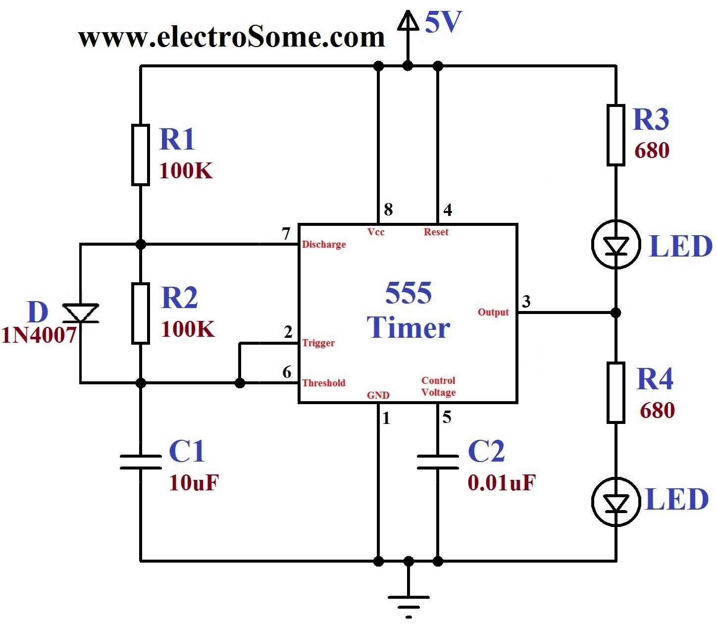
1st and 8th pins of 555 timer are used to provide power, Vcc and GND respectively. 4th is the Reset pin which is a active low input and is tide to Vcc to avoid accidental resets. 5th is the Control Voltage pin which is not used in this application, hence it is grounded via 0.01μF capacitor to avoid high frequency noises. When the output is HIGH capacitor charges to Vcc via resistor R1 and Diode. When the output is LOW capacitor discharges via resistor R2 and Discharge pin (7th) of 555 timer.
When the output is LOW (0V) upper LED glows and when the output is HIGH (5v) lower LED glows. Instead of current limiting resistors R3, R4 you may use another LED, such that two LEDs will come in series. You can use higher supply voltages if you need to drive more LEDs. LM/NE555 can work upto 16V and SE555 can work upto 18V. 555 can source or sink up to 200mA current, if you need more current use a transistor driver. You can also connect this circuit to relay for controlling incandescent lamps as shown below.
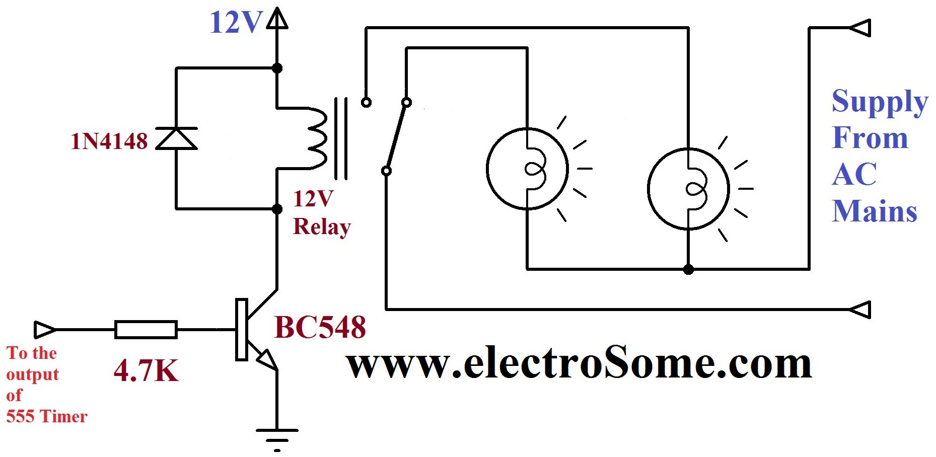
Here transistor is wired as a switch, when the base input is HIGH transistor turns ON and the relay is energized. Since the output of the 555 timer is square wave, the relay energizes and de-energizes continuously. Incandescent lamps turns ON alternatively since they are connected to Normally Open (NO) and Normally Closed (NC) of the realy output.
LED ON – OFF period is determined by the resistors R1, R2 and the capacitor C1. You can change these resistors or capacitors to adjust the time period and can be determined by the equation, T = 1.1RC.
Since the capacitor charges through R1, charging time period,
- Tcharging = THIGH = 0.693R1C1
Since the capacitor discharges through R2, discharging time period,
- Tdischarging = TLOW = 0.693R2C1
Our 555 Astable Design Tool at the bottom of the article Astable Multivibrator using 555 Timer will make your calculations simpler.
