

Temperature Controlled Fan using Arduino
Contents
Here we are going to make a temperature controlled DC fan. DHT22 sensor is used to sense the room temperature and then we adjust speed of a DC fan/motor accordingly using PWM (Pulse Width Modulation). Arduino Uno is the heart of this project and a L293D driver IC is used to drive the DC fan/motor.
Components Required
- Arduino Uno
- L293D Motor Driver IC
- DHT22 Sensor
- 16×2 LCD Display
- DC Fan/motor
- 9V Battery
- 10KΩ Potentiometer
- 220Ω Resistor
- Breadboard
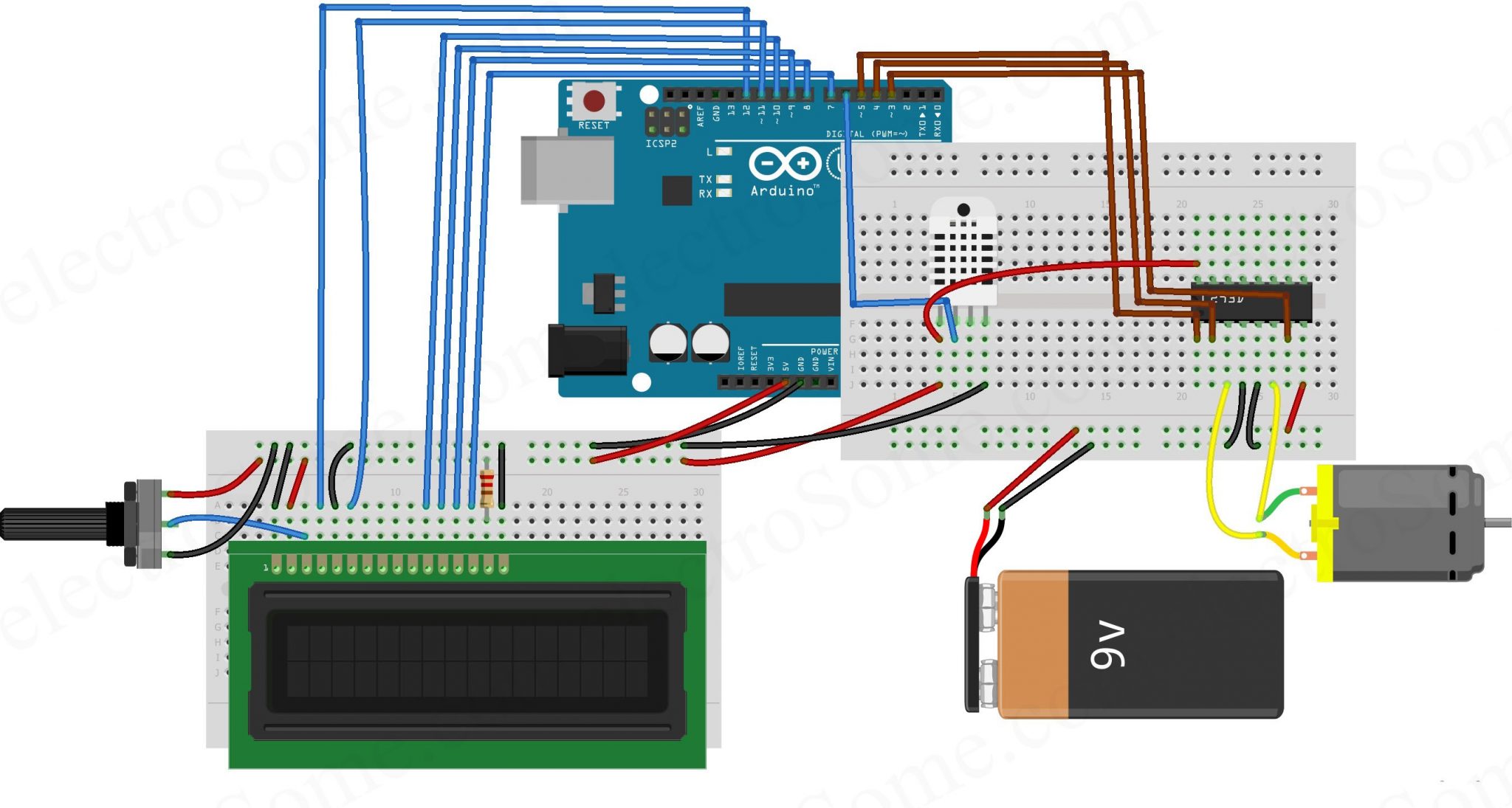
Circuit Diagram
Explanation
First we can connect L293D motor driver IC to Arduino as below. You can read articles L293D Motor Driver IC and H-Bridge Motor Driving for more information about the working of L293D.
- Connect pin 1 (Enable 1) of L293D to pin 5 of Arduino.
- Connect pin 2 (Input 1) of L293D to the pin 4 of Arduino.
- Connect pin 3 (Output 1) of L293D to one terminal of the DC motor.
- Pins 4 and 5 of the L293D are ground pins, connect these to common ground (battery ground + arduino ground).
- Connect pin 6 (Output 2) of L293D to the remaining terminal of the DC motor.
- Connect pin 7 (Input 2) of L293D to the pin 3 of Arduino.
- Pin 8 is Vcc2, which is the driver/motor power input, connect it to positive of the battery.
- Pin 16 is Vcc1, which is logic voltage input (voltage level of control signals provided by Arduino). Connect it to 5V output of Arduino.
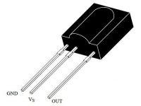
After that connect DHT22 sensor to the Arduino, it is using a single wire bus for communication.
- First pin is VCC power input, connect it to 5V output of Arduino.
- Second pin is DATA output, connect it to pin 6 of Arduino.
- Third pin is NOT USED.
- Fourth pin is Ground, connect it to ground.
Now we can connect 16×2 LCD to the Arduino.
- Pin 1 is VSS, connect it to ground.
- Pin 2 is VDD, connect it to 5V output of Arduino.
- Pin 3 is VEE, for adjusting display contrast. Connect it to the variable terminal of a potentiometer whose fixed terminals are connected to ground and 5V.
- Pin 4 is RS (Register Select), it is used to select data or command register. Connect it to pin 12 of Arduino.
- Pin 5 is R/W (Read/Write). Connect it to ground since we are only writing data to LCD in this project.
- Pin 6 is EN (Enable), it is used to indicate a valid data/command in data lines (D0 ~ D7). Connect it to pin 11 of Arduino.
- Pin 7 ~ 10 are data pins (D0 ~ D3), used to transmit data/command to LCD controller. But these pins are not used in 4 bit LCD interfacing, so connect it to ground.
- Pin 11 ~ 14 are data pins (D4 ~ D7), used to transmit data/commands to LCD controller. Connect it to Arduino pins 10, 9, 8 and 7 respectively.
Program
#include "DHT.h"           // Including DHT22 library
#include "LiquidCrystal.h" // Including LCD library

#define DHTPIN 6      // Declaring pin 6 for communicating to DHT22 sensor
#define DHTTYPE DHT22 // Declaring the type of DHT sensor we are using (DHT22 or DHT11)

DHT dht(DHTPIN, DHTTYPE);          // Declaring DHT connection and type
LiquidCrystal lcd(12,11,10,9,8,7); // Declaring LCD connections

int Motor_Pin1 = 4;  // pin 2 on L293D
int Motor_Pin2 = 3;  // pin 7 on L293D
int Enable = 5;      // pin 1 on L293D

void setup() {
  pinMode(Motor_Pin1, OUTPUT);
  pinMode(Motor_Pin2, OUTPUT);
  pinMode(Enable, OUTPUT);
  lcd.begin(16,2); // Initializes the 16x2 LCD
  dht.begin();     // Initializes DHT sensor
}

void loop() {
  lcd.clear();                        // Clear LCD

  float temp = dht.readTemperature(); // Reading the temperature in Celsius

  if (isnan(temp)) {                  // Validating received data
    lcd.print("Failed to read");
    delay(1000);
    return;
  }

  lcd.setCursor(0,0);
  lcd.print("Temp.: ");
  lcd.print(temp);      // Writing temperature in the first row
  lcd.print(" C");
  lcd.setCursor(0,1);   // Setting the position to display fan speed

  if(temp <25 ) {                 // If the temperature less than 25
    analogWrite(Enable,0);        // 0% PWM duty cycle
    lcd.print("Fan OFF ");
    delay(100);
  }
  else if(temp>=25 & temp<30) {      // If the temperature is between 25 & 30
    analogWrite(Enable, 77);         // 30% of maximum duty cycle value (255).
    lcd.print("Fan Speed: 30% ");
    delay(100);
  }
  else if(temp>=30 & temp<35) {      // If the temperature is between 30 & 35
    analogWrite(Enable, 153);        // 60% of maximum duty cycle value (255).
    lcd.print("Fan Speed: 60% ");
    delay(100);
  }
  else if(temp>=35) {                // If the temperature is above 35
    analogWrite(Enable, 255);        // 100% duty cycle
    lcd.print("Fan Speed: 100%   ");
    delay(100);
  }

  digitalWrite(Motor_Pin1, LOW);  // To drive the motor in a particular direction
  digitalWrite(Motor_Pin2, HIGH); // To drive the motor in a particular direction

  delay(2000); // 2 seconds delay
}
DHT22 Library
You need to manually add DHT library to Arduino IDE as it is not included by default. You can ignore it if you already added it. Otherwise you can do following steps for that.
- Download DHT Library from here : DHT Sensor Library.
- Open Arduino IDE.
- Go to Sketch >> Include Library >> Add .ZIP Library
- Select the downloaded ZIP file and press Open.
Explanation
First of all, we have included libraries for DHT22 and LCD. After that we have declared pins connected to DHT22, LCD and L293d motor driver.
#include "DHT.h"            // Including DHT22 library
#include "LiquidCrystal.h"  // Including LCD library

#define DHTPIN 6      // Declaring pin 6 for communicating with DHT22 sensor
#define DHTTYPE DHT22 // Declaring the type of DHT sensor we are using (DHT22 or DHT11)

DHT dht(DHTPIN, DHTTYPE);          // Declaring DHT connection and type
LiquidCrystal lcd(12,11,10,9,8,7); // Declaring the LCD connections

int Motor_Pin1 = 4;  // pin 2 on L293D
int Motor_Pin2 = 3;  // pin 7 on L293D
int Enable = 5;      // pin 1 on L293D
Next we are initializing the Arduino and modules connected to it.
void setup() {
  pinMode(Motor_Pin1, OUTPUT);
  pinMode(Motor_Pin2, OUTPUT);
  pinMode(Enable, OUTPUT);
  lcd.begin(16,2); // Initializes the 16x2 LCD
  dht.begin();     // Initializes DHT sensor
}
In the next section we are reading temperature from DHT22 sensor and storing it in a variable ‘temp’.
float temp = dht.readTemperature(); // Reading the temperature in Celsius

  if (isnan(temp)) {                // Validating received temperature (whether it is a number or not)
    lcd.print("Failed to read");
    delay(1000);
    return;
  }
Then we are displaying the temperature in LCD.
lcd.setCursor(0,0);   //Setting the cursor at the start of the LCD
lcd.print("Temp.: "); //Writing the temperature on the LCD
lcd.print(temp);      //Writing the value of temperature on the LCD
lcd.print(" C");
lcd.setCursor(0,1);   //setting the cursor at next line
In the next section we are creating 4 steps of fan speed depending on the temperature.
if(temp <25 ) {                      // If the temperature less than 25
    analogWrite(Enable,0);           // 0% PWM duty cycle
    lcd.print("Fan OFF ");
    delay(100);
  }
  else if(temp>=25 & temp<30) {      // If the temperature is between 25 & 30
    analogWrite(Enable, 77);         // 30% of maximum duty cycle value (255).
    lcd.print("Fan Speed: 30% ");
    delay(100);
  }
  else if(temp>=30 & temp<35) {      // If the temperature is between 30 & 35
    analogWrite(Enable, 153);        // 60% of maximum duty cycle value (255).
    lcd.print("Fan Speed: 60% ");
    delay(100);
  }
  else if(temp>=35) {                // If the temperature is above 35
    analogWrite(Enable, 255);        // 100$ duty cycle
    lcd.print("Fan Speed: 100%   ");
    delay(100);
  }
Hope you clearly understand the program, if you have any doubts please do comment below.
Working
DHT22 sensor is used to read the temperature to control fan speed. It can even read relative humidity also. This sensor is very easy to use and having very good accuracy compared to other sensors. We are using L293D motor driver IC for controlling DC fan/motor with Arduino. It can drive 2 DC motors and we can also control the speed by providing PWM signals.
In the program we have set four different conditions to run the DC fan. If the temperature is less than 25°C, then the DC fan will remain off and details will be displayed on the LCD. If the temperature is between 25°C and 30°C, then the DC fan will start working at low speed (30% duty cycle). Similarly if the temperature is between 30°C and 35°C, then the DC fan will run at a medium speed (60% duty cycle). If the temperature is greater than or equal to 35°C, then the DC fan will run at full speed (100% duty cycle).

I did check my all parts separately everything is OK.
Also I checked all the connection so many time ,but couldn’t figure it out the reason.
Make sure that your connections are correct and the sensor is working fine.
why i am keep getting “Failed to read” on lcd
It is used to adjust the contrast of the LCD. We can also replace it with fixed resistor.
what is the role of potentiometer??
sir im getting only 3.45 Volts from outpins of l293d i need 9v for the fan to run sir … can u help me
can i get the code in assembly
hello did you get the right code??
What is the voltage of the dc fan used?
Could you add an audible beep to this circuit? To let you know it’s kicked on?
It flashes because all of the code is inside the loop. After the loop is completed it starts all over again. So the LCD is being cleared everytime the loop completes which is why you see blinking.
Hi, I wanted to connect to 2 exhaust fan, and one normal DC fan, how I suppose to connect? Is it all connect to the L293D?
I had error with the program given plz help sir I want the right program immediately please help anybody.
I hope someone is still around to see this… I just put this together, and did get it working, but 2 questions: 1. I have a fan (4-wire), not a motor, so what wires from the fan do I use, and where should they go? 2. The display works, but it stays on for 2 seconds, flashes, stays on, flashes… why? Thanks.