

Interfacing HC-SR04 Ultrasonic Distance Sensor with ATmega32 Microcontroller
Contents
Introduction
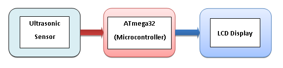
This project uses an ultrasonic sensor to indicate the distance of any object from it. Here we have made a setup based on a microcontroller in which real time distance is sensed by an ultrasonic sensor and displays measured distance on an LCD display.
Required Components
- ATmega32 Microcontroller
- HC-SR04 Ultrasonic Distance Sensor
- 16×2 LCD Display
- 5V Power Supply
Hardware
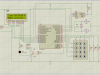
Circuit Diagram

Circuit Description
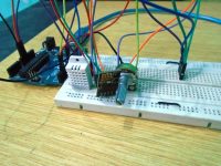
The overall circuit assembled on the breadboard contains three major components :ATmega 32 Microcontroller, Ultrasonic distance sensor and 16X2 Alphanumeric LCD display. The microcontroller is interfaced with 16X2 LCD and Ultrasonic sensor.
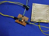
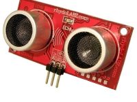
HC-SR04 Ultrasonic Sensor
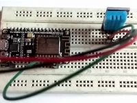
The ultrasonic distance sensor has 4 Pins: Vcc, GND, Trigger and Echo. The Vcc and GND are used to power up the sensor and are connected to power and ground rails on breadboard. Trigger is connected to PIN 14 (RX/PD0) and Echo is connected to PIN 16 (INT0/PD2) of the microcontroller.
16X2 LCD Display
There are various ways to interface the LCD display to microcontroller based on the coding technique and the platform used.
The LCD has 16 pins.
Pin no 1 and 2 are GND and Vcc respectively, and are used to power up the LCD.
The Pin no 3 VEE, which can be used to adjust the contrast of LCD by varying the potentiometer. We shall connect it to ground in our setup.
Pin no 4, 5 and 6 are the control pins of LCD and they decide the working of LCD. We shall connect these pins to PORT D of microcontroller.
- Pin 4 is RS (Register Select) and is connected to PIN 17 (PD3/INT1),
- Pin 5 is RW (Read / Write) and is connected to PIN 18 (PD4) and
- Pin 6 is E (Enable) which is connected to PIN 19 (PD5) of the microcontroller.
Pin 7 to 14 are D0-D7 which are the data lines. They are connected to PORT A of the microcontroller (PIN 40-13).
The pin 15 and 16 are for LCD back light and those pins will be connected to Vcc And Gnd.
Tools
Hardware Tools
USB ASP Programmer
To burn the program in the microcontroller.

Software Tools
Atmel Studio
To write the program and build its hex file.

Atmel Studio can be easily downloaded from the website:
ProgISp
To burn the program in microcontroller.

Source Code
Program
The following code must be burnt in the microcontroller:
// Measuring distance using ultrasonic distance sensor

#include <avr/io.h>
#include <MrLcd/MrLCDmega32.h>
#include <avr/interrupt.h>
#include <util/delay.h>
#include <stdlib.h>

static volatile int pulse = 0;
static volatile int i = 0;

int main(void)
{
  int16_t count_a = 0;
  char show_a[16];
  Initialise();
  DDRD = 0b11111011;
  _delay_ms(50);

  Initialise();

  GICR |= 1<<INT0;
  MCUCR |= 1<<ISC00;

  sei();

  while(1)
  {
    PORTD |= 1<<PIND0;
    _delay_us(15);

    PORTD &= ~(1<<PIND0);
    count_a = pulse/58;

    Send_A_String("Distance Sensor");
    GoToMrLCDLocation(1,2);
    Send_A_String("Distance=");
    itoa(count_a,show_a,10);
    Send_A_String(show_a);
    Send_A_String(" ");
    GoToMrLCDLocation(13,2);
    Send_A_String("cm");
    GoToMrLCDLocation(1,1);
  }
}

ISR(INT0_vect)
{
  if(i == 0)
  {
    TCCR1B |= 1<<CS10;
    i = 1;
  }
  else
  {
    TCCR1B = 0;
    pulse = TCNT1;
    TCNT1 = 0;
    i = 0;
  }
}
The following code uses a header file for LCD for which a library is required.
Description
1. Headers
#include <avr/io.h>
#include <MrLcd/MrLCDmega32.h>
#include <avr/interrupt.h>
#include <util/delay.h>
#include <stdlib.h>
2. Defining variables
static volatile int pulse = 0;
static volatile int i = 0;
- The variable ‘pulse’ is used to store the count value from the TCNT register.
- The variable ‘i’ is used as a flag to indicate the current status of the Echo pin.
3. Initialisation of LCD and setting up of port D as IO port
Initialise();
DDRD = 0b11111011;
_delay_ms(50);
‘Initialize()’ is a function used to initialize the LCD and is defined in the library of the LCD that has been previously made.
Next instruction sets up the function of the Pins of the port D of microcontroller. 1 means that an output device is connected at that PIN and microcontroller will write the logic there and 0 means that input device is connected there and microcontroller will read the logic from there.
“DDRD = 0b11111011”:
- DDR Stands for “Data Direction Register”
- D indicates PORTD of microcontroller
- ‘0b’ means binary
- Each bit after 0b indicates the status of each pins of port in reverse order i.e PIND7, PIND6, PIND5, PIND4, PIND3, PIND2, PIND1, PIND0.
- PIND2 is set as input pin as it is connected to the echo pin of the sensor. Thus the microcontroller will read the status of the echo PIN.
- PIND0 is set to 1 as it is connected to trigger pin of the sensor. The microcontroller will trigger the sensor by setting up logic 1 and 0 at this pin.
- We have used a few pins (PIND3, PIND4, PIND5) to connect the control pins of the LCD display. Thus to enable their use as output pins we have set them to logic high.
- Other pins that are left open are don’t care pins and can be set at any value (i.e 0 or 1).
4. Setting up the Interrupt
GICR |= 1<<INT0;
MCUCR |= 1<<ISC00;
- GICR : General Interrupt Control Registor
This Instruction is used to configure the PIN D2 as an interrupt PIN as the ECHO pin of the sensor is connected here.
- MCUCR: MCU control Register
The second instruction defines that any logical change at the INT0/PIND2 Pin will cause the microcontroller.
Thus microcontroller will be interrupted when logic goes from 0 to 1 or from 1 to 0.
These registers are specified in the datasheet of ‘Atmega32A’ and can be referred on Page no 70.
5. Defining variables
int16_t count_a = 0;
char show_a[16];
We define a variable ‘count_a’ to store the final output value after processing. After analysis it is concluded that value of pulse when divided by 58 gives the distance measure in centimeters.
The the value of “pulse/58” is stored in this variable.
‘Show_a’ variable is used to convert the ‘int’ type value to ‘char’ type value so that it can be displayed on LCD.
6. Triggering the ultrasonic sensor
PORTD |= 1<<PIND0;
_delay_us(15);
PORTD &= ~(1<<PIND0);
The PIN no 0 of port D (PIN D0) was connected to the trigger of the sensor. To trigger the sensor we need to apply a pulse of sufficient width. Here we have applied a pulse of width 15 microsecond.
- The PIN D0 is set high (5V).
- A delay of 15Microseconds is given.
- The PIN D0 is again set to Low (0v).
7. Instructions to display the output
Send_A_String("Distance Sensor");
GoToMrLCDLocation(1,2);
Send_A_String("Distance=");
itoa(count_a,show_a,10);
Send_A_String(show_a);
Send_A_String(" ");
GoToMrLCDLocation(13,2);
Send_A_String("cm");
GoToMrLCDLocation(1,1);
Send_A_String(“string”), GOTO MrLCDLocation(int x, int y ), are the functions defined in nthe LCD library.
We observe that the function “Send_A_String” uses ‘char’ type parameter but the final value ‘count_a’ is a ‘int’ type variable. Thus to convert ‘int’ type to char type we use the ‘itoa’ instruction which converts integer to string. The no 10 signifies base 10 i.e decimal no system.
8. The Interrupt Service Routine
ISR stands for interrupt service routine. It is a function that is executed when the microcontroller is interrupted.
ISR(INT0_vect)
{
  if(i == 0)
  {
    TCCR1B |= 1<<CS10;
    i = 1;
  }
  else
  {
    TCCR1B = 0;
    pulse = TCNT1;
    TCNT1 = 0;
    i = 0;
  }
}
The echo pin goes high as soon as ultrasound wave is sent and it goes low when it receives the reflected wave or when timed out. The time for which the echo pin is high is directly proportional to the distance of the obstacle from sensor.
Thus we need to calculate the time for which this pin has stayed high. For this we use the inter counter of the microcontroller.
1. When Echo Pin goes from low to high (0 to 1)
We have previously defined a variable ‘i’ that had initial value 0. When the echo PIN goes high the controller is interrupted and the ISR is executed. The condition is checked with the ‘if’ statement and the microcontroller starts the counter and also sets the value of ‘i’ to 1.
TCCR stands for TIMER COUNTER CONTROL REGITER. Setting its CS10 bit to 1 starts the timer with a prescaling of 1. The count value is stored in a register called TCNT.
2. When Echo pin goes form high to low (1 to 0)
When the echo pin goes low, microcontroller is interrupted again and again the ISR is executed. This time value of ‘i’ is 1 (We had changed it from 0 to 1 when we had started the timer).
The ‘if’ condition will be checked again. This time the timer will be stopped by setting TCCR to zero.The value that was counted will be saved in TCNT register. We will store that value in a previously defined variable ‘pulse’ and clear/ reset the value of TCNT.
Adding Header File
The Atmel Studio does not have inbuilt Library for LCD. Thus we need to add that library.
For that we need to copy the header file (‘filename.h’ type) at the location where other libraries are kept.
Go to this location in your file browser:
C:\Program Files (x86)\Atmel\Studio\7.0\toolchain\avr8\avr8-gnu-toolchain\avr\include

Make a folder here named MrLCD (You can use any name. But you will have to make changes accordingly in your program).
Download Header file here
Paste your header file in the folder.

Now you will get suggestion for this library while working in the Atmel Studio.
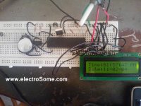
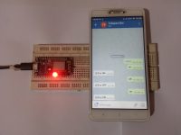
Practical Implementation
Working
This article is used to monitor the distance between ultrasonic sensor and object and it will display that monitored distance value on 16X2 LCD display. Microcontroller ATmega32 is used to control the whole process.
Ultrasonic sensor will be having transmitter and receiver in it. Transmitter continuously transmits the signal and whenever obstacle approaches the sensor then that transmitted signal hits the object, bounce back and received by ultrasonic receiver. That sensor sensed signal with respect to distance is then send to microcontroller, microcontroller in turn displays the measured distance value on LCD.

Please describe your problem in detail.
Thankyou, but the value on LCD does not change. Please help me
Please describe your problem in detail.
are you sure about this code ?? the value on the LCD is not right and I don’t know the problem
are you sure about this code ?? the value on the LCD is not right and I don’t know the problem
Thank you for your valuable feedback. I have updated the article based on your suggestions.
Thank you very much for the very useful lesson.
There are couple of notes on it.
Quote: The echo pin is the one that becomes high after it receives reflected waves.
Note: Actually the echo pin goes high as soon as ultrasound wave is sent and it goes low when it receives the reflected wave.
Also the code of interrupt function is not quite correct:
ISR(INT0_vect)
{
if(i == 1)
{
TCCR1B = 0;
pulse = TCNT1;
TCNT1 = 0;
i = 0;
}
if(i == 0)
{
TCCR1B |= 1<
Why did you divide the pulse value by 58? can you explain the calculation behind that declaration?
Thank You
thank you so much my teacher
The value on LCD does not change. What can be a problem?
Yes, it is possible. You need to configure appropriate registers for that.
Is it possible to use timer/counter 0 or timer/counter 2 instead of this. How to do it If it is possible ?
Thank you!