

Multiplexing of Seven Segment Displays with PIC Microcontroller
Contents
 When a Seven Segment Display is interface with PIC Microcontroller it needs minimum 7 pins to display a value. But real time applications like Digital Clock, Calculator, Digital Watch requires 3-6 seven segment displays. Lets assume that we need 6 digit display, ie we need 7 segment * 6 Display = 42 pins. Thus we actually need Microcontroller with 42 output pins. This is waste and not economical to use lot of pins of a Microcontroller just for display.
The simplest way to drive Seven Segment Display is by using a driver or decoder and are available for up to 4 displays. Alternatively we can drive more than one Seven Segment Display by using a technique called ‘Multiplexing’. This technique is based on the principle of Persistence of Vision of our eyes. If the frames change at a rate of 25 ( or more) frames per second, human eye can’t detect that visual change. Each display is turned on above this rate and our eyes will think that the display is turned on for whole the time.![]()
Circuit Diagram

We have used Common Cathode Seven Segment Display in this example. Pins RB0 – RB6 are connected to the A – G of the display. This will count from 000 to 999.
MikroC Code
Multiplexing Code
 PORTB = Hex(s%10);
 PORTD.F2 = 1;
 Delay_ms(10);
 PORTD.F2 = 0;
 PORTB = Hex((s/10)%10);
 PORTD.F1 = 1;
 Delay_ms(10);
 PORTD.F1 = 0;
 PORTB = Hex((s/100)%10);
 PORTD.F0 = 1;
 Delay_ms(10);
 PORTD.F0 = 0;
Where ‘s’ is an unsigned integer which counts from 000 to 999 and ‘Hex’ is a user defined function which will return Seven Segment Decoded Hex of a single digit.
First we send data through the data port, then we enable corresponding display and a appropriate delay is given. It is better to adjust the delay according to the situation after making your project.
Decoding Function
unsigned int Hex(int a)
{
 switch(a)
 {
 case 1: return 0x06;
 case 2: return 0x5B;
 case 3: return 0x4F;
 case 4: return 0x66;
 case 5: return 0x6D;
 case 6: return 0x7D;
 case 7: return 0x07;
 case 8: return 0x7F;
 case 9: return 0x6F;
 case 0: return 0x3F;
 }
}
Download Here
You can download MikroC Source Code, Proteus files etc here.
Try in real hardware, that is best. You can also try by changing the refresh rate in proteus.
Dear Ligo,
Hello and thank you for your projects, I am new to PIC and have learned a lot from here! 🙂
On this project in Proteus, I get this before the simulation and the numbers are very unstable and all 3 digits show the same number and count forward together.
Error is:
[SPICE] Gmin step [0 of 120] failed: GMIN=0.001
Let me know please how to solve this as I tried delay settings in the PIC Advance Properties dialog for the Port Pin High/Low and Port Pin Low/High delays and still not fixing. I tried 1000ms, 10ms, 2000ms already for both and each separately.
Thank you again for your time and the wonderful work you are doing here.
maselectguitar
hi can you help me to wrote a code real time on pic18f4550
Could you do an example on HI-TECH C or is it similar?
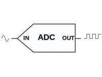
Another thing: I need to get, in two 7SEG LED, data from ADC in digital signal and XORed digital signal. So as the output signal would binar I need to use only two digits. And don’t realy know how to do it, new guy in this kind of stuff.
You can adjust delays to get stable display.
Sir Display is unstable .will this error be removed in hardware ?
Above program is intended for MikroC Pro.
You can adjust delays after making the hardware.
why if im still using your coding,when i compile it,still have errors?..how to solve that?
The display is flickring its not stable
i want to develope a code (C or basic language) for traffic signal count down timer, any one can make,, i will pay
Yes.,
PORTB.F0 is equivalent to RB0_bit
sir can you please tell me what are the meanings of F1,F2,F3 ?
can you explain it?
why cant we directly RD0_bit=0 or ect ?
i m want to display the value 4500-5500 on 4 digit 7 seg using pic16f72 with the help of a POT. everything going well bt 7 seg display has flickering effect. so plz help …i have tried many times bt it cant be removed…so plz tell me the causes why this happening.
can u pls help me to make code
My Mail id: [email protected]
I think you should use 7 segment decoders… as multiplexing of 12 led may not work properly….. better use a 4511 7 segment decoder for each 7 segment and.. enable it at different times…
can any one pls help me to make code for the attached schematic? four rows of three 7 seg display to show 3 digit numbers.
hi
Use a serial in parallel out shift register…….
I WONT TO SAND 8 BIT SERIAL DATA ON OHER SEVEN SAGMENT DISPLAY WIRELESS.SO HELP ME IF POSSIBAL BOTH SIDE HARDWERE AND SOFTWERE
MY EMAILID IS [email protected].
It is used to make delay between counts… delay depends on the value of D….. If we set delay by delay function, it will turn off the display for that time..
sir why did u make D count 10 before increasing S
first login : http://www.electrosome.com/wp-login.php
Then go to the link :http://www.electrosome.com/wp-content/plugins/download-monitor/download.php?id=6
please somebody help me im loging in but i cant download the complete file
please i think that theres a problem here sir
all my reagards