
Contents
An Astable Multivibrator or a Free Running Multivibrator is the multivibrator which has no stable states. Its output oscillates continuously between its two unstable states without the aid of external triggering. The time period of each states are determined by Resistor Capacitor ( RC ) time constant.
Astable Multivibrator using Transistors – Circuit

In the above diagram we can find two transistors which is wired as a switch. Please do read the article Transistor as A Switch. When a transistor is ON, its collector and emitter act as a short circuit. But when it is OFF they acts as open circuit. So in the above circuit when a transistor is in OFF state its collector will have the voltage Vcc and when it is ON its collector will be grounded. When one transistor is ON the other will be OFF. The OFF time of transistor is determined by RC time constant.
When the circuit is switched on, one of the transistor will be more conducting than the other due imbalance in the circuit or difference in the parameters of the transistor. Gradually the more conducting transistor will be driven to Saturation and the less conducting transistor will be driven to Cutoff.
Working
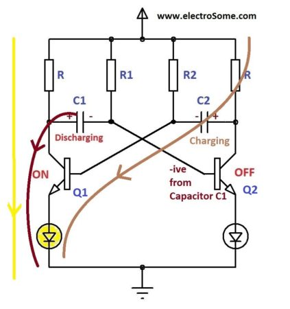
- When the circuit is switched on one transistor will driven to saturation (ON) and other will driven to cutoff (OFF). Consider Q1 is ON and Q2 is OFF.
- During this time Capacitor C2 is charging to Vcc through resistor R.
- Q2 is OFF due to the -ive voltage from the discharging capacitor C1 which is charged during the previous cycle. So the OFF time of Q2 is determined by R1C1 time constant.

- After a time period determined by R1C1 time constant the capacitor C1 discharges completely and starts charging in reverse direction through R1.
- When the Capacitor C1 charges to a voltage sufficient provide base emitter voltage of 0.7V to the transistor Q2, it turns ON and capacitor C2 starts dischargeing.
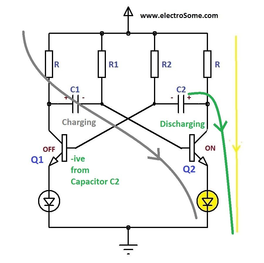
- The negative voltage from the capacitor C2 turns off the transistor Q1 and the capacitor C1 starts charging from Vcc through resistor R and base emitter of transistor Q2. Thus the transistor Q2 remains in ON state.
- As in the previous state, when the capacitor C2 discharges completely it starts charging towards opposite direction through R2.
- When the voltage across the capacitor C2 is sufficient to turn ON transistor Q1, Q1 will turn ON and capacitor C1 starts discharging.
- This process continuous and produces rectangular waves at the collector of each transistors.
- Note : Charging time is very less compared to discharging time.
Design
R – Collector Resistor
The resistance R should be designed to limit the collector current Ic with in a safe limit.
R = V/Ic , where V is the voltage across the resistor R.
In normal cases, V = (Vcc – Vce) = (Vce – 0.3) but when an emitter load like LED is connected,
V = (Vcc – Vce – Vled) , where Vled is the voltage drop across LED.
Usually the maximum collector current Ic will be much higher than than the current required for emitter load such as LED. In these cases Ic should be chosen in such a way that it should not exceed the max current limit of emitter load.
So,
- R = (Vcc – Vce – Vload) / Ic
R1 & R2 – Base Resistors
R1 & R2 should be chosen such that it should give the required collector current during saturation state.
- Min. Base Current, Ibmin = Ic / β, where β is the hFE of the transistor
- Safe Base Current,Ib = 10x Ibmin= 3 x Ic / β
- R1, R2 = (Vcc – Vbe) / Ib
T1 & T2 – Time Period
- T2 = OFF Period of transistor Q1 = ON Period of Transistor Q2 = 0.693R2C2
- T1 = OFF Period of transistor Q2 = ON Period of Transistor Q1 = 0.693R1C1
From these equations we can find the value of C1 and C2.
Duty Cycle
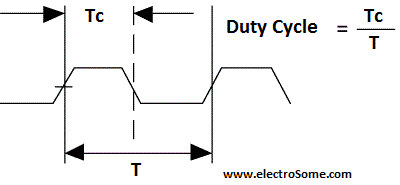
It is the ratio of time Tc during which the output is high to total time period T of the cycle.
Thus here, Duty Cycle = Toff/(Toff + Ton) when the output is taken from the collector of the transistor T.
Calculator
Making Edges Sharp
Due to the initial capacitor charging current, LOW -> HIGH edge of output is not sharp. If you need sharp edges you can use 2 additional resistors and diodes.
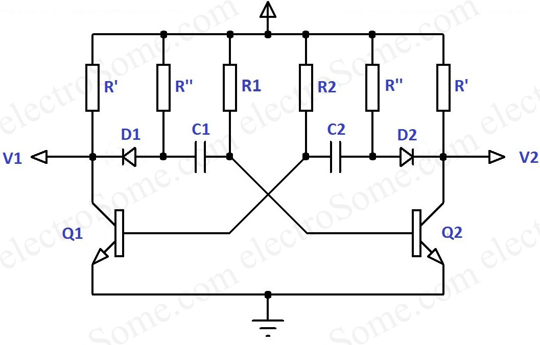
The diodes D1, D2 will prevent charging of capacitor through collector resistor R’. Thus capacitors C1, C2 will charge through R”, makes the output waves sharp.