Contents
Automatic night lamp as the name suggests is for turning ON and OFF the lamp automatically without the need of human interventions. It senses the light intensity from surroundings and find whether its day or night. And it automatically turns ON when the surrounding is dark and it turns OFF when it receives light from surroundings. A sensor called LDR is used to detect the light intensity. This project finds wide outdoor applications in streets, gardens and public places where it finds difficulty to appoint a person to operate the lights.
Components Required
- Light Dependent Resistor (LDR)
- LM358 Op-Amp
- Resistor 22KΩ
- Resistor 10KΩ
- Preset 10KΩ
- BC547 transistor
- 1N4148 diode
- 12V Relay
Circuit Diagram
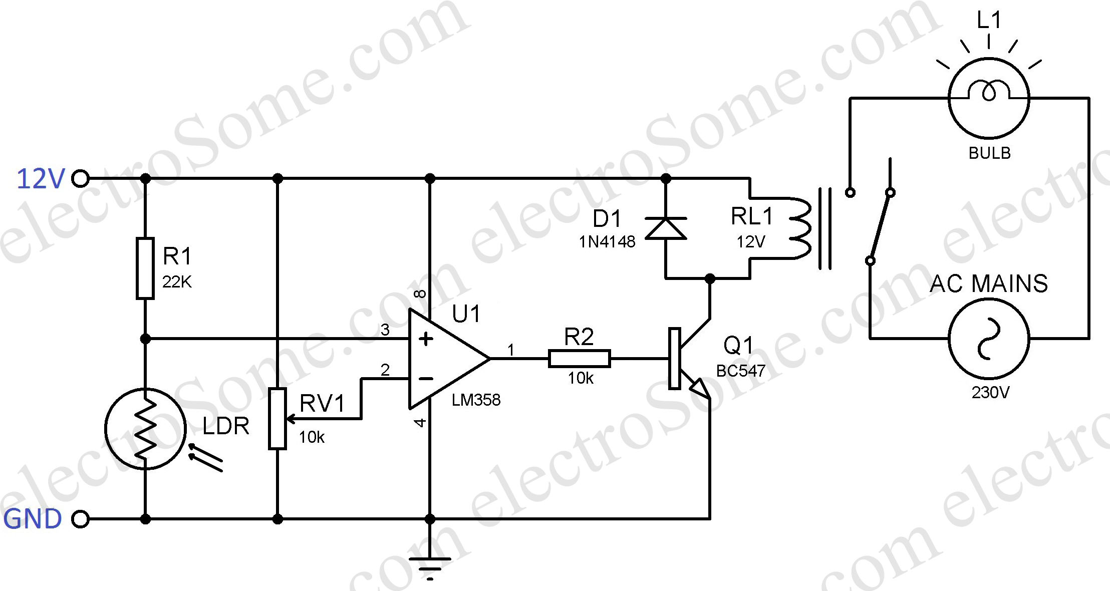
Working
The main part of this circuit is the light dependent resistor (LDR). It is a sensor which is a particular kind of resistor whose resistance decreases when exposed to light. Likewise it offers high resistance in dark. The resistance value changes from few 100 ohms to mega ohm range. The LDR is placed in a potential divider network. So voltage across LDR changes with intensity of light. Voltage across the LDR is given to the positive terminal of a comparator. Now a reference voltage is required to compare with the voltage across LDR. That reference voltage is made by using the pot or preset. So this preset can be used to adjust the sensitivity of the circuit. Next is the comparator made using LM358 op-amp which compares the voltage levels at its two inputs and gives output accordingly. If the voltage at positive terminal is greater, the output will be high and if the voltage at negative terminal is greater, the output will be low. That is if it is dark, resistance across LDR is high, so voltage drop across the LDR is high and voltage at positive terminal will be greater than the reference voltage. Therefore output of comparator will be high. The output of comparator is given to a transistor wired as a switch. Since enough voltage appears across the base emitter junction, the transistor conducts and current passes through the relay coils. So relay switches its contact and the bulb glows. Bulb is connected to the NO (Normally Open) pin of relay as it should be off when the relay coils are not energized. If the output of comparator is low, then transistor will be in OFF stage. So no current flows through the relay and bulb remains in OFF stage.
You can choose a voltage between 3 to 32V for powering this circuit depending of the relay coil voltage. I choose 12V since 12V relays are very common in the market.
Note : You should keep the LDR in such a way that light from lamp L1 (connected to this circuit) will not fall on it.
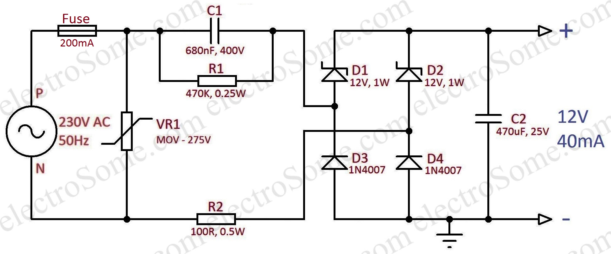
Power Supply
I prefer to use a capacitor dropper power supply. I used the following circuit for that, it is a 12V, 40mA supply. Please read the article, Transformerless Capacitor Power Supply for more details about it.
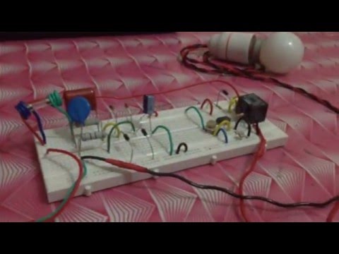
Video