Contents
A Digital Clock can be made easily by using PIC Microcontroller, DS1307 and a 16×2 LCD. I have already posted about Interfacing DS1307 RTC with PIC Microcontroller. The DS1307 RTC can work either in 24-hour mode or 12-hour mode with AM/PM indicator. It automatically adjusts for months fewer than 31 days including leap year compensation up to year 2100. DS1307 comes with built-in power sensing circuit which senses power failures and automatically switches to back up supply. We can provide a 3V CMOS Battery for that. Communication between PIC Microcontroller and DS1307 takes place through I²C Bus.
Components Required
- PIC 16F877A Microcontroller
- DS1307 RTC
- 16×2 LCD
- 8MHz Crystal
- 32.768KHz Crystal for RTC
- 3V Battery
- 2x 22pF Capacitors
- 0.1μF Capacitor
- 4x 10KΩ Resistors
- 10KΩ Preset
- 2x 2.2KΩ Resistors
- 4.7KΩ Resistor
- 3x Micro Switches (Push Button)
- 5V Power Supply
Prerequisites
I recommend reading following articles before going further.
Circuit Diagram – Digital Clock
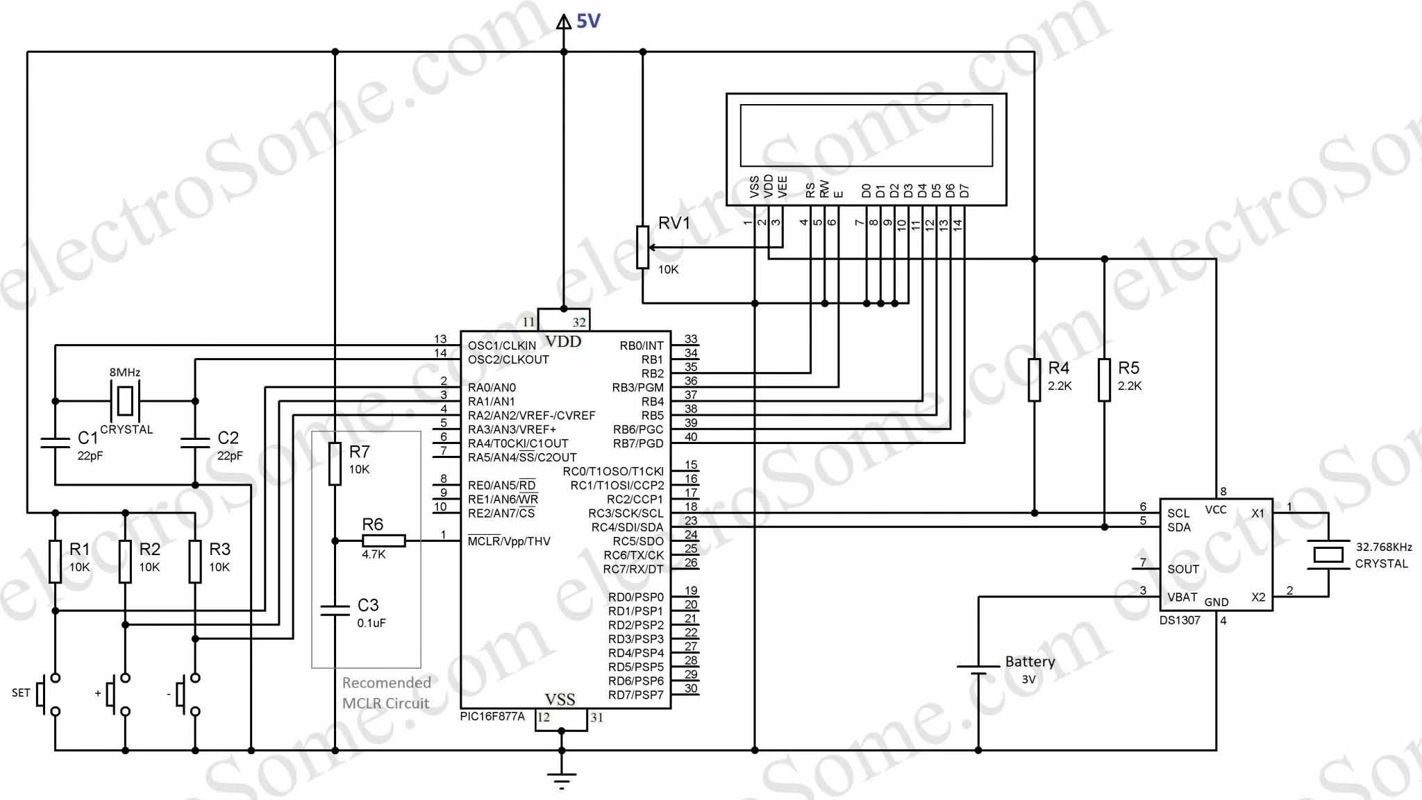
I hope that you can easily understand the circuit diagram. The circuit is powered using a 5V power supply. 8MHz crystal is connected to PIC Microcontroller to provide necessary clock for the operation. An RCR (Resistor-Capacitor-Resistor) made using 10KΩ, 0.1µF, 4.7KΩ is connected to MCLR pin of PIC Microcontroller as recommended by Microchip. It will work fine even if you tie MCLR pin directly to VDD but Microchip doesn’t recommends it. DS1307 RTC is connected to PIC microcontroller via I2C bus. Pull up resistors connected to I2C bus is very important, please make sure that you are using correct values for it. An additional power supply (usually a battery or button cell) is connected to DS1307 RTC for running the clock during power failures. This circuit will function even without that battery also but the clock will stop and reset during power failure.
MikroC Code
// LCD module connections
sbit LCD_RS at RB2_bit;
sbit LCD_EN at RB3_bit;
sbit LCD_D4 at RB4_bit;
sbit LCD_D5 at RB5_bit;
sbit LCD_D6 at RB6_bit;
sbit LCD_D7 at RB7_bit;
sbit LCD_RS_Direction at TRISB2_bit;
sbit LCD_EN_Direction at TRISB3_bit;
sbit LCD_D4_Direction at TRISB4_bit;
sbit LCD_D5_Direction at TRISB5_bit;
sbit LCD_D6_Direction at TRISB6_bit;
sbit LCD_D7_Direction at TRISB7_bit;
// End LCD module connections

unsigned short read_ds1307(unsigned short address)
{
  unsigned short r_data;
  I2C1_Start();
  I2C1_Wr(0xD0); //address 0x68 followed by direction bit (0 for write, 1 for read) 0x68 followed by 0 --> 0xD0
  I2C1_Wr(address);
  I2C1_Repeated_Start();
  I2C1_Wr(0xD1); //0x68 followed by 1 --> 0xD1
  r_data=I2C1_Rd(0);
  I2C1_Stop();
  return(r_data);
}

void write_ds1307(unsigned short address,unsigned short w_data)
{
  I2C1_Start(); // issue I2C start signal
  //address 0x68 followed by direction bit (0 for write, 1 for read) 0x68 followed by 0 --> 0xD0
  I2C1_Wr(0xD0); // send byte via I2C (device address + W)
  I2C1_Wr(address); // send byte (address of DS1307 location)
  I2C1_Wr(w_data); // send data (data to be written)
  I2C1_Stop(); // issue I2C stop signal
}

unsigned char BCD2UpperCh(unsigned char bcd)
{
  return ((bcd >> 4) + '0');
}

unsigned char BCD2LowerCh(unsigned char bcd)
{
  return ((bcd & 0x0F) + '0');
}

int Binary2BCD(int a)
{
  int t1, t2;
  t1 = a%10;
  t1 = t1 & 0x0F;
  a = a/10;
  t2 = a%10;
  t2 = 0x0F & t2;
  t2 = t2 << 4;
  t2 = 0xF0 & t2;
  t1 = t1 | t2;
  return t1;
}

int BCD2Binary(int a)
{
  int r,t;
  t = a & 0x0F;
  r = t;
  a = 0xF0 & a;
  t = a >> 4;
  t = 0x0F & t;
  r = t*10 + r;
  return r;
}

int second;
int minute;
int hour;
int hr;
int day;
int dday;
int month;
int year;
int ap;

unsigned short set_count = 0;
short set;

char time[] = "00:00:00 PM";
char date[] = "00-00-00";

void main()
{
  I2C1_Init(100000); //DS1307 I2C is running at 100KHz
  CMCON = 0x07;   // To turn off comparators
  ADCON1 = 0x06;  // To turn off analog to digital converters
  TRISA = 0x07;
  PORTA = 0x00;
  Lcd_Init();                        // Initialize LCD
  Lcd_Cmd(_LCD_CLEAR);               // Clear display
  // Lcd_Cmd(_LCD_CURSOR_OFF);          // Cursor off
  Lcd_Cmd(_LCD_BLINK_CURSOR_ON);
  Lcd_out(1,1,"Time:");
  Lcd_out(2,1,"Date:");

  do
  {
    set = 0;
    if(PORTA.F0 == 0)
    {
      Delay_ms(100);
      if(PORTA.F0 == 0)
      {
        set_count++;
        if(set_count >= 7)
        {
          set_count = 0;
        }
      }
    }
    if(set_count)
    {
      if(PORTA.F1 == 0)
      {
        Delay_ms(100);
        if(PORTA.F1 == 0)
          set = 1;
      }
      if(PORTA.F2 == 0)
      {
         Delay_ms(100);
         if(PORTA.F2 == 0)
           set = -1;
      }
      if(set_count && set)
      {
        switch(set_count)
        {
          case 1:
                  hour = BCD2Binary(hour);
                  hour = hour + set;
                  hour = Binary2BCD(hour);
                  if((hour & 0x1F) >= 0x13)
                  {
                    hour = hour & 0b11100001;
                    hour = hour ^ 0x20;
                  }
                  else if((hour & 0x1F) <= 0x00)
                  {
                     hour = hour | 0b00010010;
                     hour = hour ^ 0x20;
                  }
                  write_ds1307(2, hour); //write hour
                  break;
          case 2:
                  minute = BCD2Binary(minute);
                  minute = minute + set;
                  if(minute >= 60)
                    minute = 0;
                  if(minute < 0)
                    minute = 59;
                  minute = Binary2BCD(minute);
                  write_ds1307(1, minute); //write min
                  break;
          case 3:
                  if(abs(set))
                  write_ds1307(0,0x00); //Reset second to 0 sec. and start Oscillator
                  break;
          case 4:
                  day = BCD2Binary(day);
                  day = day + set;
                  day = Binary2BCD(day);
                  if(day >= 0x32)
                    day = 1;
                  if(day <= 0)
                    day = 0x31;
                  write_ds1307(4, day); // write date 17
                  break;
          case 5:
                  month = BCD2Binary(month);
                  month = month + set;
                  month = Binary2BCD(month);
                  if(month > 0x12)
                    month = 1;
                  if(month <= 0)
                    month = 0x12;
                  write_ds1307(5,month); // write month 6 June
                  break;
          case 6:
                  year = BCD2Binary(year);
                  year = year + set;
                  year = Binary2BCD(year);
                  if(year <= -1)
                    year = 0x99;
                  if(year >= 0x50)
                    year = 0;
                  write_ds1307(6, year); // write year
                  break;
        }

      }
    }

    second = read_ds1307(0);
    minute = read_ds1307(1);
    hour = read_ds1307(2);
    hr = hour & 0b00011111;
    ap = hour & 0b00100000;
    dday = read_ds1307(3);
    day = read_ds1307(4);
    month = read_ds1307(5);
    year = read_ds1307(6);

    time[0] = BCD2UpperCh(hr);
    time[1] = BCD2LowerCh(hr);
    time[3] = BCD2UpperCh(minute);
    time[4] = BCD2LowerCh(minute);
    time[6] = BCD2UpperCh(second);
    time[7] = BCD2LowerCh(second);

    date[0] = BCD2UpperCh(day);
    date[1] = BCD2LowerCh(day);
    date[3] = BCD2UpperCh(month);
    date[4] = BCD2LowerCh(month);
    date[6] = BCD2UpperCh(year);
    date[7] = BCD2LowerCh(year);

    if(ap)
    {
      time[9] = 'P';
      time[10] = 'M';
    }
    else
    {
      time[9] = 'A';
      time[10] = 'M';
    }
    Lcd_out(1, 6, time);
    Lcd_out(2, 6, date);
    Delay_ms(100);
  }while(1);
}
You can download the MikroC Source Code and Proteus Files etc at the end of this article. Here I explains the Source Code and different functions used in it.
The Three points to be noted while editing or creating program for this project:
- DS1307 RTC is fully Binary Coded Decimal (BCD) clock/calender. So the data read from DS1307 should be converted to required format according to our needs and data to be written to DS1307 should be in BCD format.
- Library for Interfacing LCD With PIC Microcontroller of MikroC needs Character or String Data. So data to be displayed in the LCD Screen should be converted to Character.
- Addition and Subtraction cannot be directly applied on BCD. Here I first convert BCD to Binary. Then addition and subtraction can be simply applied on Binary. Then the Binary is converted back to BCD.
Functions that are used for reading and writing data from DS1307 are explained in the article Interfacing DS1307 with PIC Microcontroller please refer it. BCD2UpperCh() and BCD2LowerCh() are the two functions used to convert BCD to Character. Hour, Minute, Second, Date, Month and Year data are stored in DS1307 in separate 8-bit registers in BCD format. We read the data of these registers to access time/date. BCD2UpperCh() converts most significant 4 bits to corresponding character and BCD2LowerCh() converts least significant 4 bits to corresponding character.
The BCD2Binary() converts the BCD data read from the RTC to corresponding Binary for addition or subtraction and Binary2BCD converts the Binary back to BCD.
Bit 6 of Hour register is defined as the 24-hour or 12-hour mode selection bit. When this bit is made high, 12-hour mode is selected and Bit 5 will represent AM/PM (Logic High represents PM).
Note : During the first setup, you might need to set the time to clock to start running.
If you have any doubts regarding the Program please do Comment.
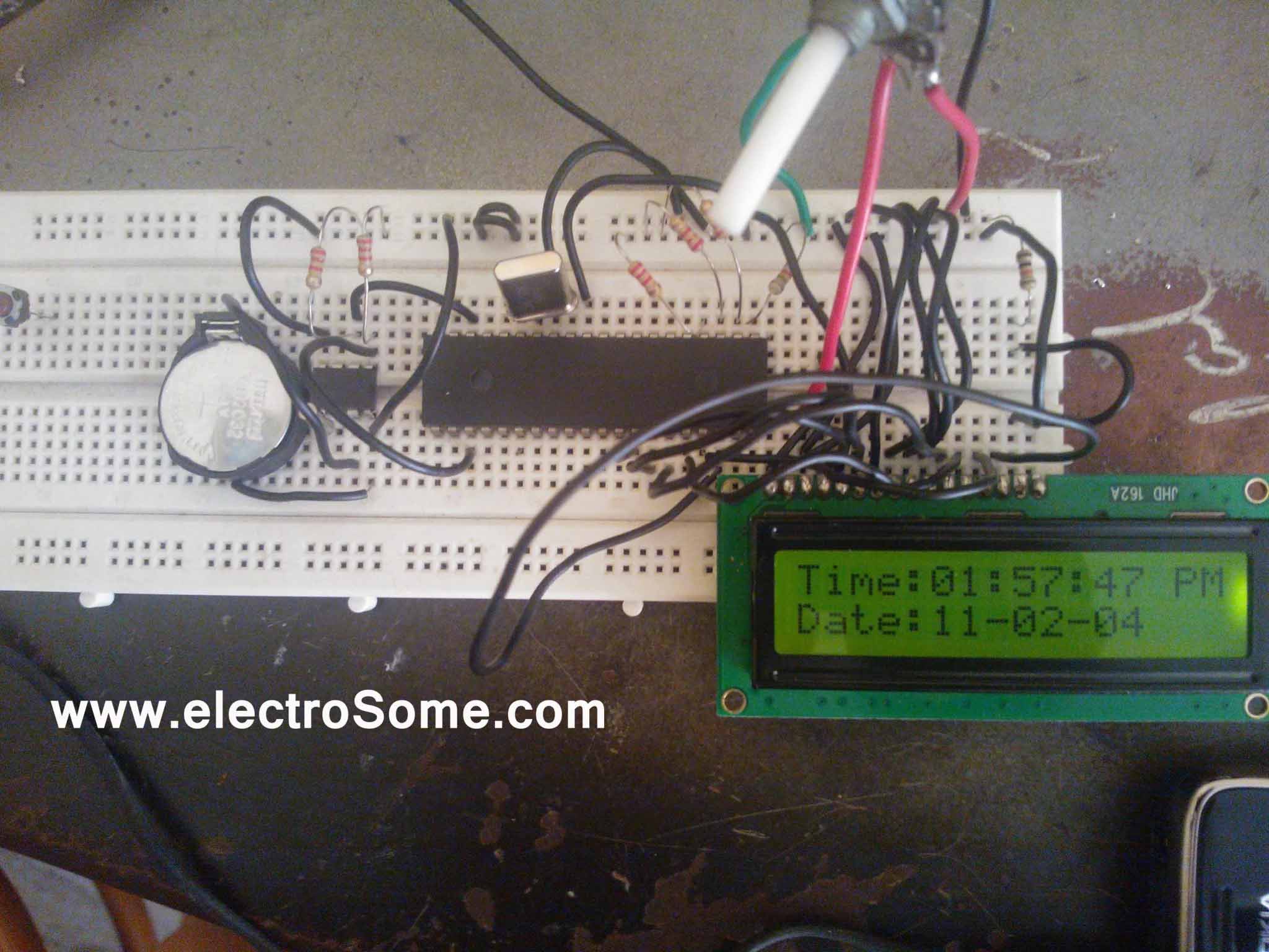
Output
Here is the photograph of this project tested in our lab.
Download Here
You can download complete project files here.