Contents
In communication systems, Frequency Modulation (FM) is the process in which information (message signal) is transmitted over a carrier wave by varying its instantaneous frequency. The difference between instantaneous frequency and central frequency of the carrier will be directly proportional to the instantaneous value of the amplitude of message signal. 555 Timer wired in Astable Mode can be used for generating Frequency Modulated (FM) waves. Please read the article Astable Multivibrator using 555 Timer for more details about the circuit. In astable multivibrator we don’t use the 5th (Control Voltage) pin of 555 but here we fed the message signal to this pin which results in the variation of frequency.
Circuit Diagram

8th and 1st pin of the 555 are used for giving power, Vcc and GND respectively. 4th pin is the Reset pin which is a active low input, since it is tied to Vcc. When the output is high, capacitor C1 charges to Vcc through R1 and D. When the output is low, capacitor discharges through resistor R2 and 7th of the IC. This charging and discharging time periods determines the time period of output. Message signal is fed to 5th (Control Voltage) pin of the IC through a coupling capacitor and the output can be taken from the 3ed pin of the IC.
Working
I hope that you read the working of Astable Multivibrator using 555 Timer. Central frequency or Carrier frequency of the generated FM can be determined from the expression, fo = 1/(1.4RC), where R = R1 = R2 and C = C1.
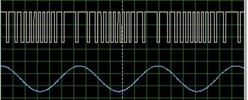
When an input voltage (say V) is given to Control Voltage pin, the upper and lower comparator reference changes to voltages V and V/2. So when the capacitor voltage becomes less than V/2, output becomes high and the capacitor starts charging to Vcc through resistor R1 and diode D. When the the capacitor voltage becomes greater than V, output becomes low and the capacitor starts discharging through resistor R2 and 7th pin of the IC. So the time period is proportional to the input voltage V. So as V increases, time period of the output wave increases and when V decreases time period of the output wave decreases.
Output
Design
- fo = 1/(1.4RC), where R = R1 = R2 and C = C1
- Coupling capacitor C3 is designed in such a way that it can couple the input message signal.
You can use our 555 Astable Multivibrator Calculator in the bottom of the article Astable Multivibrator using 555 Timer for easy calculations.