Contents
In this tutorial we will learn how to blink an LED using STM32 ARM Cortex-M microcontroller STM32F103C8T6 and Keil IDE. This is a beginners hello world project. Here we use STM32CubeMx for generating basic startup code and Hardware Abstraction Layer (HAL) for Keil IDE.
Components Required
Hardware
- STM32 Blue Pill Development Board STM32F103C8T6
- ST-Link-V2
- Jumper Wires
Software
- Keil IDE
- STM32CubeMX
STM32 Development Board
This is one of the smallest and low-cost ARM Cortex development board available in the market. It uses STM32F103C8T6, an STM32 ARM Cortex-M3 microcontroller. It provides two onboard crystal oscillators, 8MHz for main oscillator and 32KHz for RTC (Real Time Clock).

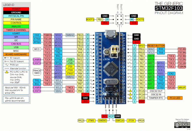
STM32F103C8T6
STM32F103C8T6 is a 32-bit microcontroller manufactured by STMicroelectronics having ARM Cortex-M3 Architecture. The part number indicates below specifications :
- STM : Manufactures name STMicroelectronics
- 32 : 32-bit ARM architecture
- F103 : Indicate the architecture ARM Cortex M3
- C : 48 pins
- 8 : 64 KB Flash Memory
- T : package type LQFP
- 6 : Operating Temperature – 40°C to 85°C
Specifications
- Digital Pins : 32 pins
- Analog Pins : 10 pins
- PWM Pins : 15 pins
- ADC Resolution : 12 bit
- PWM Resolution : 16 bit
- 2x I2C , 2x SPI , 1x CAN , 2x USART , 1x USB .
- Internal Flash : 64 KB
- SRAM : 20 KB
- Max. Clock Frequency : 72 MHz
- Operating Voltage : 2.0 to 3.6 V
- Debugging : Serial, JTAG
Programming
Generating Code with STM32CubeMX
Here we are using Keil IDE for programming STM32. It will be a cumbersome job to write complete code from scratch as STM32 is a complex ARM Cortex-M3 microcontroller. To make this simple we are using a GUI software STM32CubeMX supplied by STMicroelectronics.
Follow the below steps accordingly:
- Download and install STM32CubeMX and Keil IDE.
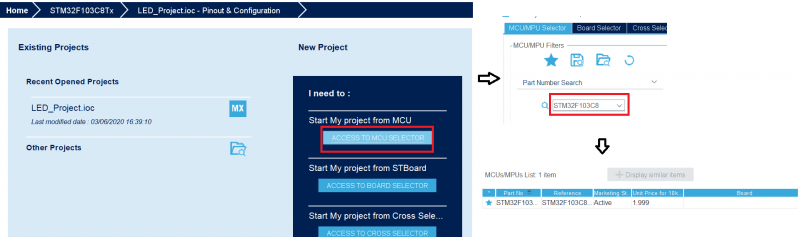
- Open the CubeMX software and click on the new project and select the microcontroller as STM32F103C8. Then double click on the STM32F103C8 at the right panel.

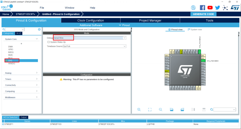
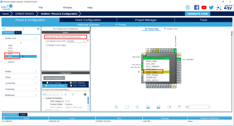
- Next, a new window will be opened where you need to change SYS Debug to Serial Wire and RCC of High-Speed Clock or HSC to Crystal/Ceramic Resonator as shown in the below fig.

- Now in the right panel as shown in the below figure, click on the pin of the chip where you want to attach the LED and I have chosen PC13. Select that particular pin where you want to blink the LED as GPIO_output by right-clicking on that pin.
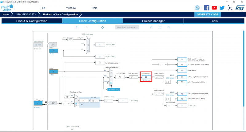
- Click the Clock Configuration and change the HCLK (MHz) to 72 and press Enter.
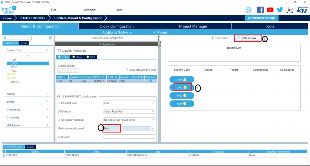
- Now go to System View and select GPIO then change the Maximum Output speed as High as shown below.

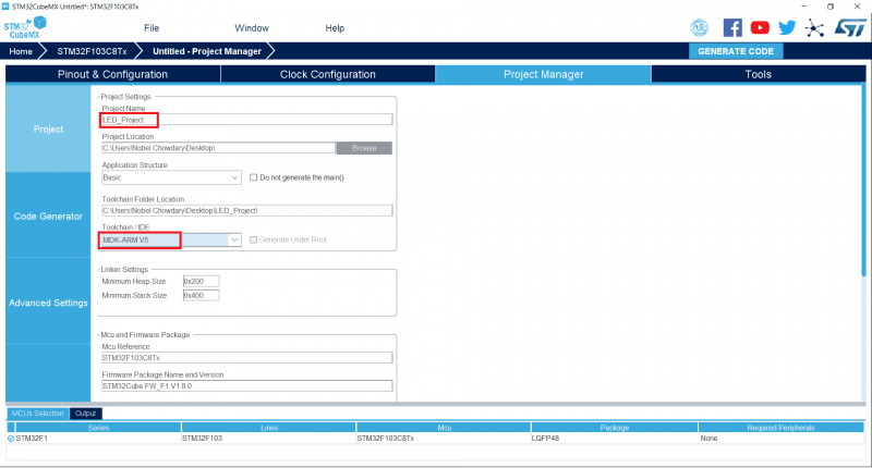
- Open the Project Manager and give the name of the project as LED_Project and change the toolchain/IDE as MDK-ARM V5.
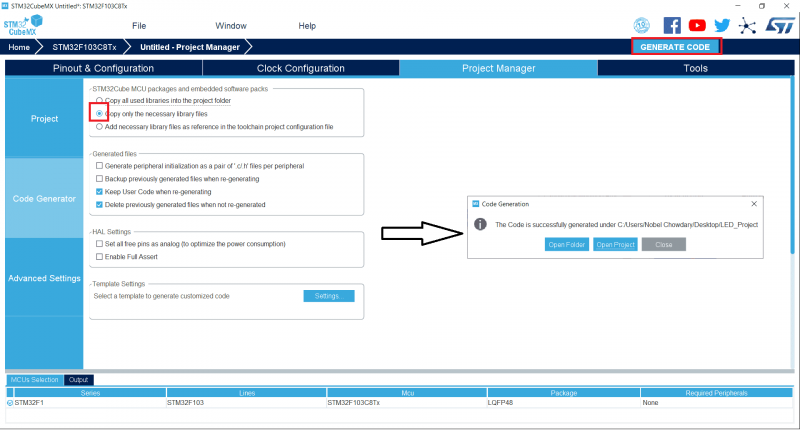
- Next on the same window click on the Code Generator and change the option as ‘Copy only the necessary library files’ and click on the GENERATE CODE. Now you can find an option to Open Project. Click on it will open the Keil project with the selected settings and configurations.
- Now in the Keil Software, click on the main.c you will find the code. There you need to change three lines of code so the work will be done.

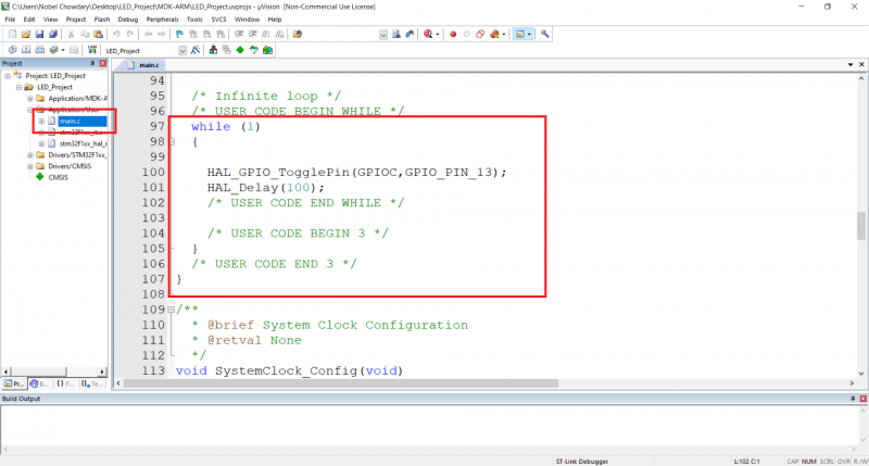
Adding LED Blinking
- As shown above in the while(1) add the code and the two lines code is shown below.
HALL_GPIO_TogglePin(GPIOC,GPIO_PIN_13);
HAL_Delay(1000);- Next press F7 to build the code and once it is built you press F8 to load the code so in the output you can find the commands that programming is done.
- Now the LED blinks as per the delay given.
- By this programming the STM32 using Keil is successfully done.
Complete Main Program
/* USER CODE BEGIN Header */
/**
******************************************************************************
* @file : main.c
* @brief : Main program body
******************************************************************************
* @attention
*
* <h2><center>© Copyright (c) 2020 STMicroelectronics.
* All rights reserved.</center></h2>
*
* This software component is licensed by ST under BSD 3-Clause license,
* the "License"; You may not use this file except in compliance with the
* License. You may obtain a copy of the License at:
* opensource.org/licenses/BSD-3-Clause
*
******************************************************************************
*/
/* USER CODE END Header */
/* Includes ------------------------------------------------------------------*/
#include "main.h"
/* Private includes ----------------------------------------------------------*/
/* USER CODE BEGIN Includes */
/* USER CODE END Includes */
/* Private typedef -----------------------------------------------------------*/
/* USER CODE BEGIN PTD */
/* USER CODE END PTD */
/* Private define ------------------------------------------------------------*/
/* USER CODE BEGIN PD */
/* USER CODE END PD */
/* Private macro -------------------------------------------------------------*/
/* USER CODE BEGIN PM */
/* USER CODE END PM */
/* Private variables ---------------------------------------------------------*/
/* USER CODE BEGIN PV */
/* USER CODE END PV */
/* Private function prototypes -----------------------------------------------*/
void SystemClock_Config(void);
static void MX_GPIO_Init(void);
/* USER CODE BEGIN PFP */
/* USER CODE END PFP */
/* Private user code ---------------------------------------------------------*/
/* USER CODE BEGIN 0 */
/* USER CODE END 0 */
/**
* @brief The application entry point.
* @retval int
*/
int main(void)
{
/* USER CODE BEGIN 1 */
/* USER CODE END 1 */
/* MCU Configuration--------------------------------------------------------*/
/* Reset of all peripherals, Initializes the Flash interface and the Systick. */
HAL_Init();
/* USER CODE BEGIN Init */
/* USER CODE END Init */
/* Configure the system clock */
SystemClock_Config();
/* USER CODE BEGIN SysInit */
/* USER CODE END SysInit */
/* Initialize all configured peripherals */
MX_GPIO_Init();
/* USER CODE BEGIN 2 */
/* USER CODE END 2 */
/* Infinite loop */
/* USER CODE BEGIN WHILE */
while (1)
{
HAL_GPIO_TogglePin(GPIOC, GPIO_PIN_13);
HAL_Delay(1000);
/* USER CODE END WHILE */
/* USER CODE BEGIN 3 */
}
/* USER CODE END 3 */
}
/**
* @brief System Clock Configuration
* @retval None
*/
void SystemClock_Config(void)
{
RCC_OscInitTypeDef RCC_OscInitStruct = {0};
RCC_ClkInitTypeDef RCC_ClkInitStruct = {0};
/** Initializes the CPU, AHB and APB busses clocks
*/
RCC_OscInitStruct.OscillatorType = RCC_OSCILLATORTYPE_HSI;
RCC_OscInitStruct.HSIState = RCC_HSI_ON;
RCC_OscInitStruct.HSICalibrationValue = RCC_HSICALIBRATION_DEFAULT;
RCC_OscInitStruct.PLL.PLLState = RCC_PLL_ON;
RCC_OscInitStruct.PLL.PLLSource = RCC_PLLSOURCE_HSI_DIV2;
RCC_OscInitStruct.PLL.PLLMUL = RCC_PLL_MUL16;
if (HAL_RCC_OscConfig(&RCC_OscInitStruct) != HAL_OK)
{
Error_Handler();
}
/** Initializes the CPU, AHB and APB busses clocks
*/
RCC_ClkInitStruct.ClockType = RCC_CLOCKTYPE_HCLK|RCC_CLOCKTYPE_SYSCLK
|RCC_CLOCKTYPE_PCLK1|RCC_CLOCKTYPE_PCLK2;
RCC_ClkInitStruct.SYSCLKSource = RCC_SYSCLKSOURCE_PLLCLK;
RCC_ClkInitStruct.AHBCLKDivider = RCC_SYSCLK_DIV1;
RCC_ClkInitStruct.APB1CLKDivider = RCC_HCLK_DIV2;
RCC_ClkInitStruct.APB2CLKDivider = RCC_HCLK_DIV1;
if (HAL_RCC_ClockConfig(&RCC_ClkInitStruct, FLASH_LATENCY_2) != HAL_OK)
{
Error_Handler();
}
}
/**
* @brief GPIO Initialization Function
* @param None
* @retval None
*/
static void MX_GPIO_Init(void)
{
GPIO_InitTypeDef GPIO_InitStruct = {0};
/* GPIO Ports Clock Enable */
__HAL_RCC_GPIOC_CLK_ENABLE();
__HAL_RCC_GPIOD_CLK_ENABLE();
__HAL_RCC_GPIOA_CLK_ENABLE();
/*Configure GPIO pin Output Level */
HAL_GPIO_WritePin(LED_GPIO_Port, LED_Pin, GPIO_PIN_SET);
/*Configure GPIO pin : LED_Pin */
GPIO_InitStruct.Pin = LED_Pin;
GPIO_InitStruct.Mode = GPIO_MODE_OUTPUT_PP;
GPIO_InitStruct.Pull = GPIO_NOPULL;
GPIO_InitStruct.Speed = GPIO_SPEED_FREQ_LOW;
HAL_GPIO_Init(LED_GPIO_Port, &GPIO_InitStruct);
}
/* USER CODE BEGIN 4 */
/* USER CODE END 4 */
/**
* @brief This function is executed in case of error occurrence.
* @retval None
*/
void Error_Handler(void)
{
/* USER CODE BEGIN Error_Handler_Debug */
/* User can add his own implementation to report the HAL error return state */
/* USER CODE END Error_Handler_Debug */
}
#ifdef USE_FULL_ASSERT
/**
* @brief Reports the name of the source file and the source line number
* where the assert_param error has occurred.
* @param file: pointer to the source file name
* @param line: assert_param error line source number
* @retval None
*/
void assert_failed(uint8_t *file, uint32_t line)
{
/* USER CODE BEGIN 6 */
/* User can add his own implementation to report the file name and line number,
tex: printf("Wrong parameters value: file %s on line %d\r\n", file, line) */
/* USER CODE END 6 */
}
#endif /* USE_FULL_ASSERT */
/************************ (C) COPYRIGHT STMicroelectronics *****END OF FILE****/
Circuit Diagram

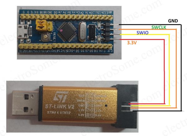
Description
- 3.3 V pin to: ST-Link 3.3 V
- DIO pin to ST-Link SWDIO
- CLK pin tp ST-Link SWCLK
- GND pin to ST-LINK GND
Video
Conclusion
Hope you understood about basic programming of STM32F103C8T6. I recommend you the watch above video for more details. Please feel free to comment below if you have any doubts.