
Contents
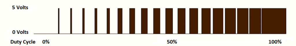
PWM (Pulse Width Modulation) is a powerful technique used to generate analog voltage using digital signals. It has a wide variety of applications such as controlling average power delivered to a load, generating analog voltage level, sine wave generation and DC Motor speed control. PWM signals are ON-OFF signals (hence the name Pulse) whose ON duration are changed (hence Width Modulation) according to our requirements. The fraction of time period for which the signal is ON to total time period is termed as Duty Cycle.
CCP Modules are available with a number of PIC Microcontrollers which can be used to generate PWM waves. CCP Stands for Capture/Compare/PWM. For programming this module in Hi-Tech C we should require a good hardware knowledge. Here for demonstration we are using PIC 16F877A.
CCP – Capture/Compare/PWM Modules
PIC 16F877A has two CCP modules named as CCP1 and CCP2. Each CCP Module has a 16 Bit register which can operate as :
- 16 Bit Capture Register
- 16 Bit Compare Register
- PWM Duty Cycle Register
This article deals only with PWM operation of CCP Modules. It can produce up to 10-bit resolution PWM output. Since CCP1 and CCP2 output are multiplexed with PORTC (RC2 and RC1), TRIS<2> and TRIS<1> must be cleared to make these pins output. CCP1 and CCP2 modules are similar in operation and you cannot set different frequencies for them, because both modules uses Timer 2 for their operation.
Working
The simplified block diagram of CCP module in PWM mode is shown below.
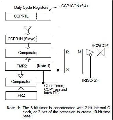
CCP modules uses Timer 2 for their operation. Period of the generated PWM waves is determined by the value in the PR2 register. Values of Timer 2 and PR2 are compared every-time using a comparator. When these values become equal, Timer 2 will be reset and output will become HIGH.
Duty cycle is determined by the value in CCPR1L and CCP1CON<5:4>. These registers can be written any time. So to avoid glitches in the PWM output, this duty cycle value is latched to CCPR1H and a 2 bit internal latch when there is a match between Timer 2 and PR2.
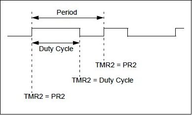
Then the value in CCPR1H and 2 bit internal latch is compared with Timer 2. When a match occurs output will become LOW as shown in the above diagram.
Note : The value of Duty Cycle value should not be greater than Time Period (PR2) value, if so the CCP pin will not be cleared.
The PWM resolution can be find using the following equation.

The following steps should be taken while configuring the PIC CCP module for PWM operation.
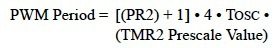
- Set the PWM Period by writing to the PR2 register and the PWM period can be calculated using the following equation.
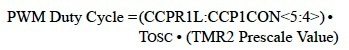
- Set the Duty Cycle of the PWM by writing to CCPR1L register and CCP1CON<5:4>. The PWM Duty Cycle can be find using the following equation and it should not exceed the PWM Period.
- Make CCP pins output by clearing the corresponding TRIS register bits.
- Set the Timer 2 (TMR2) prescale value and enable the timer by writing to T2CON register.
- Then configure the CCP module for PWM operation.
Circuit Diagram
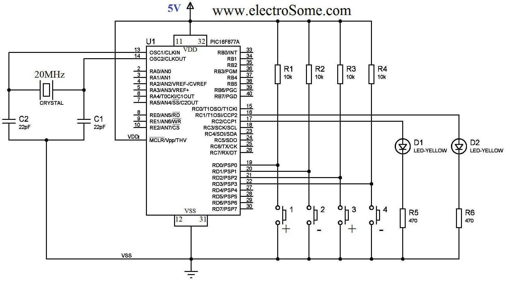
The above circuit diagram can be used for demonstrate the working of CCP modules in PWM mode. A 20MHz crystal is used for providing the necessary clock for the operation of the microcontroller and 22pF capacitors are used to stabilize the operation of crystal. Outputs of CCP1 and CCP2 modules are connected to LEDs using a series resistor to limit current. Four Switches are used to vary the duty cycle of the PWM waves. 10Ω resistors are used to Pull Up the inputs pins of microcontroller used for reading switches, when the switch is not ON.
Hi-Tech C Code
#include<htc.h>

#define _XTAL_FREQ 20000000
#define TMR2PRESCALE 4
long freq;

int PWM_Max_Duty()
{
  return(_XTAL_FREQ/(freq*TMR2PRESCALE);
}

PWM1_Init(long fre)
{
  PR2 = (_XTAL_FREQ/(fre*4*TMR2PRESCALE)) - 1;
  freq = fre;
}

PWM2_Init(long fre)
{
  PR2 = (_XTAL_FREQ/(fre*4*TMR2PRESCALE)) - 1;
  freq = fre;
}

PWM1_Duty(unsigned int duty)
{
  if(duty<1024)
  {
    duty = ((float)duty/1023)*PWM_Max_Duty();
    CCP1X = duty & 2;
    CCP1Y = duty & 1;
    CCPR1L = duty>>2;
  }
}

PWM2_Duty(unsigned int duty)
{
  if(duty<1024)
  {
    duty = ((float)duty/1023)*PWM_Max_Duty();
    CCP2X = duty & 2;
    CCP2Y = duty & 1;
    CCPR2L = duty>>2;
  }
}

PWM1_Start()
{
  CCP1M3 = 1;
  CCP1M2 = 1;
  #if TMR2PRESCALAR == 1
    T2CKPS0 = 0;
    T2CKPS1 = 0;
  #elif TMR2PRESCALAR == 4
    T2CKPS0 = 1;
    T2CKPS1 = 0;
  #elif TMR2PRESCALAR == 16
    T2CKPS0 = 1;
    T2CKPS1 = 1;
  #endif
  TMR2ON = 1;
  TRISC2 = 0;
}

PWM1_Stop()
{
  CCP1M3 = 0;
  CCP1M2 = 0;
}

PWM2_Start()
{
  CCP2M3 = 1;
  CCP2M2 = 1;
  #if TMR2PRESCALE == 1
    T2CKPS0 = 0;
    T2CKPS1 = 0;
  #elif TMR2PRESCALE == 4
    T2CKPS0 = 1;
    T2CKPS1 = 0;
  #elif TMR2PRESCALE == 16
    T2CKPS0 = 1;
    T2CKPS1 = 1;
  #endif
    TMR2ON = 1;
    TRISC1 = 0;
}

PWM2_Stop()
{
  CCP2M3 = 0;
  CCP2M2 = 0;
}

void main()
{
  unsigned int i=0,j=0;
  PWM1_Init(5000);
  PWM2_Init(5000);
  TRISD = 0xFF;
  PWM1_Duty(0);
  PWM2_Duty(0);
  PWM1_Start();
  PWM2_Start();
  do
  {
    if(RD0 == 0 && i<1000)
      i=i+10;
    if(RD1 == 0 && i>0)
      i=i-10;
    if(RD2 == 0 && j<1000)
      j=j+10;
    if(RD3 == 0 && j>0)
      j=j-10;
    PWM1_Duty(i);
    PWM2_Duty(j);

    __delay_ms(50);
  }while(1);
}
I thinks the code is self explanatory. PWM1_Init(frequency) and PWM2_Init(frequency) are used to initialize the CCP1 and CCP2 module in PWM mode with a particular frequency. You cannot have different frequencies for the two PWM modules. PWM1_Duty(duty) and PWM2_Duty(duty) are used to set the duty cycle of the PWM waves. The parameter duty can be any value ranging from 0 to 1023. Calling PWM1_Start() and PWM2_Start() will start generating PWM waves and calling PWM1_Stop() and PWM2_Stop() will stop the PWM waves.
Download
You can download Hi-Tech C and Proteus files here…
Video
[youtube video_id=”ekNqRfMHP8E” width=”880″ height=”495″]