Contents

What is I2C (I²C) ?
I²C (Read as “i-squared cee”; Inter-Integrated Circuit) is a multi-master serial single-ended computer bus invented by Philips, used to attach low-speed peripherals to a embedded system,cellphone, motherboard, or other electronic device and is generally referred to as “two-wire interface”. It consists of two wires called SCL and SDA. SCL is the clock line which is used to synchronise all the data transfers through I2C bus and SDA is the data line. It also need a third line as reference line (ground or 0 volt). A 5v power should be also be given to the device for its working. The main thing to be noted is that both SCL and SDA are Open Drain drives. Which means that the chip can drive its low output but can’t drive high output. Thus we must provide two pull up resistors to 5v for SCL and SDA, to make it to drive high output as shown in the fig.

Selection of Pull Up Resistors
1. The rise time of SCL and SDA voltages will depend up on the value of pull up resistor and I2C bus capacitance. Thus pull up resistor should be selected according to the I2C bus frequency being used.
2. The higher value of pull up resistor is limited by the rise time and the lower vale of pull up resistor is limited by the drive strength (IOL max) of the SDA and SCL drivers. If the pull up resistor is very low , the SCL and SDA outputs might not be establish enough low voltage.
I recommend you to use 1.8K pull up resistors.
MikroC PRO for PIC Microcontroller provide built-in libraries for I2C devices. DS1307 works as a slave device on I2C bus. Register access can be obtained by implementing a START and followed by device identification address. Then each registers can be accessed sequentially by using its address until a STOP condition is executed.
Device Address : 0X68 = 1101000
Reading Data from DS1307
MikroC Code
unsigned short read_ds1307(unsigned short address)
 {
   unsigned short temp
   I2C1_Start();
   I2C1_Wr(0xD0);
   I2C1_Wr(address);
   I2C1_Repeated_Start();
   I2C1_Wr(0xD1);
   temp = I2C1_Rd(0);
   I2C1_Stop();
   return(temp);
 }
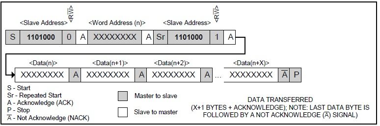
I2C1_Start() check whether the I2C bus is free and issues start signal. I2C1_Wr() sends data bytes through the I2C bus. We first send address bit (address 0X68 + direction bit (0 for write, 1 for read) 0x68 followed by 0 –> 0xD0). Then we select the required Time keeper register using its address (0 – Seconds, 1 – Minute, 2- Hour etc) to read data. In these operations data is send from PIC to RTC. Address of Time keeper registers can be find from the following table.

I2C1_Repeated_Start() will provide repeated start signal for reading the data, since data transfer takes place from RTC to PIC. Then we read the data of the selected register using I2C1_Rd(0) (if the parameter is given as 0, it will not sends acknowledge signal). Then STOP signal is issued by using I2C1_Stop().

Writing Data to DS1307
MikroC Code
void write_ds1307(unsigned short address, unsigned short w_data)
 {
   I2C1_Start();
   I2C1_Wr(0xD0);
   I2C1_Wr(address);
   I2C1_Wr(w_data);
   I2C1_Stop();
 }

Writing Data from DS1307 is smiler to reading data from it. After selecting the required register for writing data, the data to be written is send using the I2C1_Wr().
I already mentioned that DS1307 RTC can be run either in 12-hour mode or 24-hour mode. See the Time Keeper Registers Table, Bit 6 of Hour register is defined as the 24-hour or 12-hour mode selection bit. When this bit is made high, 12-hour mode is selected and Bit 5 will represent AM/PM (Logic High represents PM). When Bit 6 is made low, 24-hour mode will be selected and Bit 5 will be used for representing Hour.
Note: Hours Value must be re-entered when the Hour mode is changed.