
Contents
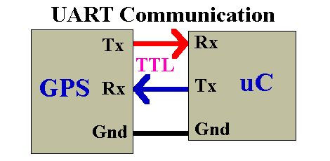
UART stands for Universal Asynchronous Receiver / Transmitter. It is a very popular serial communication interface which provides Full Duplex communication between two devices. UART uses two data lines for sending (TX) and receiving (RX) data. Ground/Reference of both devices should be made common. As the name indicates it is an asynchronous communication interface, which means that it doesn’t need to send CLOCK along with data as in synchronous communications. UART is the communication interface used by our old computer’s RS-232 port.
Some of the Microchip’s PIC Microcontroller has built in USART Module. USART stands for Universal Synchronous Asynchronous Receiver Transmitter and it can be configured in following modes.
- UART – Asynchronous (Full Duplex)
- USRT Master – Synchronous (Half Duplex)
- USRT Slave – Synchronous (Half Duplex)
In this tutorial we will learn how to use UART Mode of USART Module using MPLAB XC8 Compiler. For demonstration we are using PIC 16F877A microcontroller.
PIC 16F877A USART Module
USART Registers
TXSTA – Transmit Status and Control Register
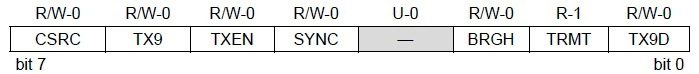
- Bit 0 TX9D : This is the 9th bit of data in the 9 bit transmission mode which is commonly used as a Parity Bit.
- Bit 1 TRMT : This is the Transmit Shift Register (TSR) status bit. This can be used to check whether the data written to transmit register is transmitted or not. When the TRS is empty this bit is set and when the TSR is full this bit will be 0.
- Bit 2 BRGH : This is the High Baud Rate Select bit for Asynchronous mode operation and is unused in Synchronous mode. Setting this bit selects High Speed and clearing this bit selects Low Speed baud rates. You will can see the baud rate calculation later in this article.
- Bit 3 Unimplemented : This bit is unimplemented and will read as 0.
- Bit 4 SYNC : This is the USART Mode select bit. Setting this bit selects Synchronous mode while clearing this bit selects Asynchronous mode.
- Bit 5 TXEN : Setting this bit enables the transmission. In the synchronous mode operation CREN and SREN bits of RCSTA register overrides this bit.
- Bit 6 TX9 : When this bit is set it enables the 9 bit transmission otherwise 8 bit transmission is used. 9th bit in the 9 bit transmission mode is commonly used as parity bit.
- Bit 7 CSRC : Clock Source Select Bit, this bit has no application in the Asynchronous mode operation of USART module. It is used to select master or slave mode in Synchronous mode operation.
RCSTA – Receive Status and Control Register

- Bit 0 RX9D : This is the 9th bit of Received Data and is commonly used as Parity Bit.
- Bit 1 OERR : Overrun Error bit. A high at this bit indicates that Overrun error has occured.
- Bit 2 FERR : Framing Error bit. 1 at this bit stands for Framing Error while 0 stands for No Framing Error.
- Bit 3 ADDEN : Address Detect Enable bit. This bit is applicable only in Asynchronous 9 bit mode. Setting this bit enables Address Detect.
- Bit 4 CREN : Continuous Receive Enable bit. Setting this bit will enable Continuous Receive. In the Synchronous Mode CREN overrides SREN.
- Bit 5 SREN : Single Receive Enable bit. This bit has no effect on Asynchronous mode and Synchronous Slave mode. Setting this bit will enables Single Receive. This bit will cleared after the reception is complete.
- Bit 6 RX9 : Setting this bit enables 9 bit reception otherwise it will be in 8 bit reception mode.
- Bit 7 SPEN : Serial Port Enable bit. Setting this bit enables serial port and configures RC7, RC6 as serial port pins.
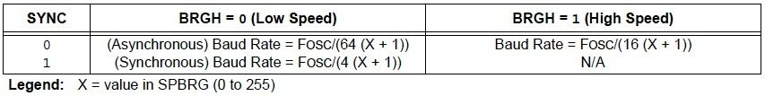
USART Baud Rate Generator (BRG)
Baud Rate Generator provides the required clock for the data transmission and reception. USART module has a dedicated 8 bit baud rate generator which supports both Synchronous and Asynchronous modes. The 8-bit SPBRG register controls the time period of this free running timer. In Asynchronous mode BRGH, 2nd bit of TXSTA register also controls the generated baud rate but in Synchronous mode it is ignored. Baud Rate can be calculated from the following equations, where FOSC is the clock frequency of the microcontroller.
MPLAB XC8 Programming
Initializing UART
char UART_Init(const long int baudrate)
{
  unsigned int x;
  x = (_XTAL_FREQ - baudrate*64)/(baudrate*64);   //SPBRG for Low Baud Rate
  if(x>255)                                       //If High Baud Rage Required
  {
    x = (_XTAL_FREQ - baudrate*16)/(baudrate*16); //SPBRG for High Baud Rate
    BRGH = 1;                                     //Setting High Baud Rate
  }
  if(x<256)
  {
    SPBRG = x;                                    //Writing SPBRG Register
    SYNC = 0;                                     //Setting Asynchronous Mode, ie UART
    SPEN = 1;                                     //Enables Serial Port
    TRISC7 = 1;                                   //As Prescribed in Datasheet
    TRISC6 = 1;                                   //As Prescribed in Datasheet
    CREN = 1;                                     //Enables Continuous Reception
    TXEN = 1;                                     //Enables Transmission
    return 1;                                     //Returns 1 to indicate Successful Completion
  }
  return 0;                                       //Returns 0 to indicate UART initialization failed
}
Note : 6th and 7th bit of TRISC registers are set as prescribed in the datasheet.
Sending Data Through UART
Writing a Character
void UART_Write(char data)
{
  while(!TRMT);
  TXREG = data;
}
Checking Transmit Register
char UART_TX_Empty()
{
  return TRMT;
}
Writing Text
void UART_Write_Text(char *text)
{
  int i;
  for(i=0;text[i]!='\0';i++)
    UART_Write(text[i]);
}
The following function can be used to write a string or array of characters to UART. It is accomplished by continuous use of character writing function UART_Write().
Receiving Data Through UART
Data Received or Not
The following function can be used to check whether the data is ready to read from the Receive Register. It uses the flag bit RCIF which will be set when the data reception is completed.
char UART_Data_Ready()
{
  return RCIF;
}
Reading a Character
The following function wait till the reception is complete and reads 8 bit data from the Receive Register.
char UART_Read()
{
  while(!RCIF);
  return RCREG;
}
Reading Text
The following function can be used to read a desired length of text or sequence of characters continuously.
void UART_Read_Text(char *Output, unsigned int length)
{
  unsigned int i;
  for(int i=0;i<length;i++)
  Output[i] = UART_Read();
}
For simplifying the program readability we put all the above functions to a header file ‘uart.h’. Thus you just need to include this header file and use required functions. For demonstrating the working of these functions we are using the following example.
PIC to PIC Communication using UART
In this example we are controlling LEDs connected to a PIC using Switches connected to another PIC Microcontroller. For the sake of explanation call these microcontrollers Slave and Master respectively. In the circuit diagram given below a DIP 8 Switch is connected to PORTB of the Master Microcontroller which is configured as Input Port. When a Switch is turned ON, the corresponding pin will be Grounded (LOW). Data Read from the PORTB of Master Microcontroller is send to Slave Microcontroller using UART interface. The Slave Microcontroller writes the received data to its PORTB which is configured as Output. Thus LED’s connected to Slave Microcontroller will Glow depending upon the status of the DIP Switch connected to the Master Microcontroller.
Circuit Diagram
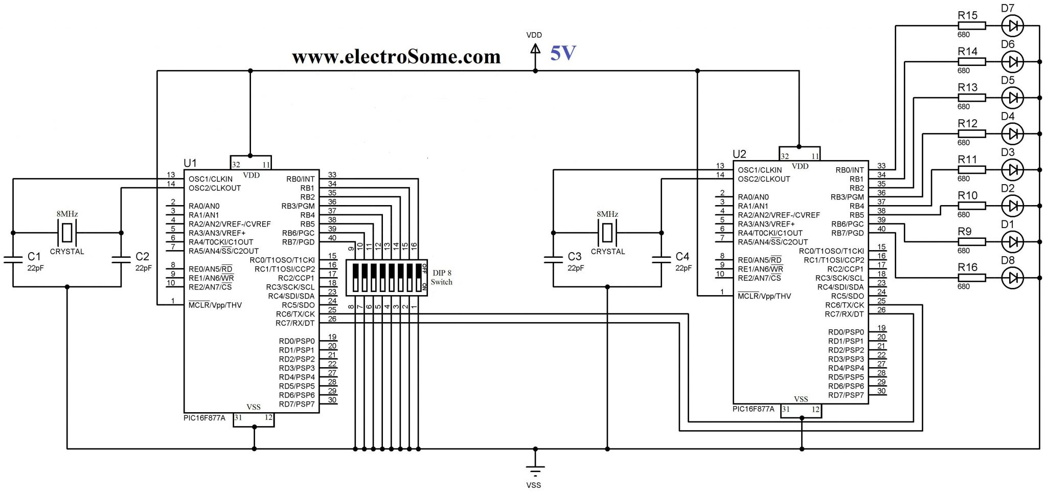
Note 1 : TX of Master Microcontroller is connected to RX of Slave Microcontroller and RX of Master Microcontroller is connected to the TX of Slave Microcontroller.
Note 2 : Instead of using PULL UP or PULL DOWN resistors along with switch, we are using INTERNAL PULL UP of PORTB which is enabled in the program.
MPLAB XC8 Codes
Master Code
#define _XTAL_FREQ 8000000
#include <xc.h>
#include <pic16f877a.h>
#include "uart.h"

// BEGIN CONFIG
#pragma config FOSC = HS
#pragma config WDTE = OFF
#pragma config PWRTE = OFF
#pragma config BOREN = ON
#pragma config LVP = OFF
#pragma config CPD = OFF
#pragma config WRT = OFF
#pragma config CP = OFF
//END CONFIG

void main()
{
  TRISB = 0xFF; //PORTB as Input
  nRBPU = 0;    //Enables PORTB Internal Pull Up Resistors
  UART_Init(9600);

  do
  {
    UART_Write(PORTB);
    __delay_ms(100);
  }while(1);
}
Slave Code
#define _XTAL_FREQ 8000000
#include <xc.h>
#include <pic16f877a.h>
#include "uart.h"
// BEGIN CONFIG
#pragma config FOSC = HS
#pragma config WDTE = OFF
#pragma config PWRTE = OFF
#pragma config BOREN = ON
#pragma config LVP = OFF
#pragma config CPD = OFF
#pragma config WRT = OFF
#pragma config CP = OFF
//END CONFIG

void main()
{
  TRISB = 0x00; //PORTB as Output
  UART_Init(9600);

  do
  {
    if(UART_Data_Ready())
       PORTB = UART_Read();
    __delay_ms(100);
  }while(1);
}
Want to See the Output ?

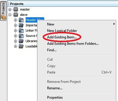
Note : Don’t forget to copy the header file ‘uart.h’ to your project folder and add it to project tree when you create a new project.
Download
You can download entire project files here…