
Contents
A lot of you may heard about microcontrollers and its applications. Well it is a bit difficult to start learning microcontrollers. And the guides and tutorials also do not start from zero level which makes learning far more difficult than anticipated. I have tried to start from zero level in here also. All you need is the simplest knowledge of electronics or digital circuits. But you surely should have a decent knowledge of C language.
The software for programming Microchip microcontrollers comes by the name MPLAB IDE. MPLAB is the name of the software and IDE stands for Integrated Development Environment. IDE means that the software itself has all or most of the features that is needed. MPLAB IDE can perform the following operations :
- Source code editing
- Project management
- Machine code generation from Assembly
- Device simulation
- Device emulation
- Device programming
Hence it is called an Integrated Development Environment.
Some things should be clear before starting the tutorial. We can write programs for the PIC microcontrollers in MPLAB but the syntax and code depends upon the library, which may be different from family to family and even a lot of libraries are available for the same family of microcontrollers too.
We are discussing about the Hi-Tech C Compiler library (HTC) for MPLAB in this tutorial. It is used for programming the microcontrollers of series 16F which will be enough for the beginner users. Now if you want to have very high performance applications through microcontrollers then you need to go to higher and more powerful family of microcontrollers like 18F, 24F series and for them the programming library is different. But as the 16F series microcontrollers are 8 bit and support clock rates up to 20 MHz, they are useful in most of our non-commercial applications.
So let’s cut directly to the chase. The software MPLAB IDE comes with integrated HTC compiler library from the version 8.56 on wards.
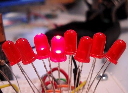
Let’s start our first project, Blinking LED using PIC 16F877A. 16F877A is a very commonly used PIC microcontroller.
- Download and Install MPLAB IDE with Hi-Tech C compiler
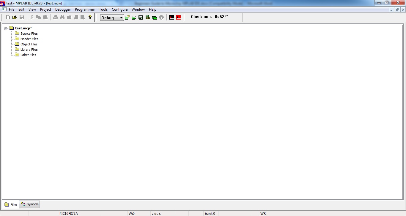
- Open MPLAB IDE
- Click on Project >> Project Wizard
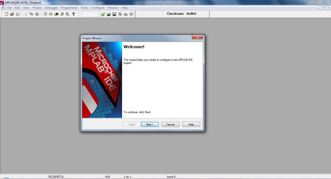
- Click on Next

- Select PIC 16F877A and click Next
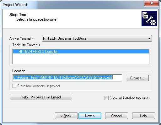
- Select Hi-Tech C compiler as show above and click Next
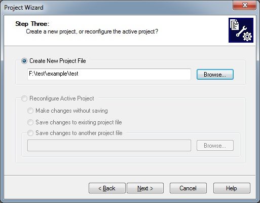
- Select Project path, give a file name and click Next

- Add required files to Project (Not required here) and click Next

- Click Finish to complete project creation
Next step is writing the program. All the information about writing programs which include its commands, operations and the microcontroller registers are available on the datasheet and Hi-Tech Toolsuite guide. But I will also try to make you understand the first steps so that the datasheet and guide may prove useful. You can start making your own programs at the end of this tutorial.
Now let us view a program for 16F877A where 8 LED are connected at the PORT B (8 pins of port B, from pin no 33-40). This programs blinks the LEDs which means the LEDs remain on for a second and off for another second.
Hi-Tech C Code
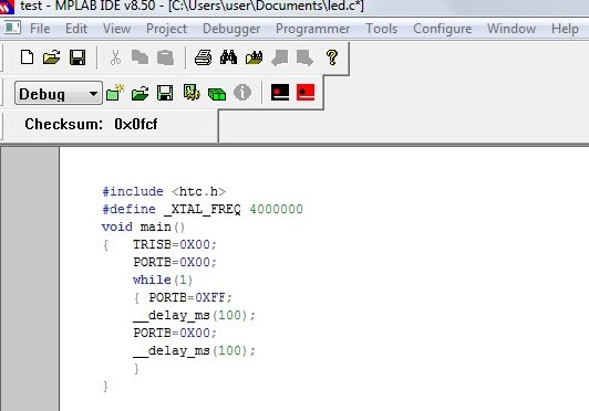
#include <htc.h>
#define _XTAL_FREQ 8000000
void main()
{
  TRISB=0X00;
  PORTB=0X00;
  while(1)
  {
    PORTB=0XFF;
    __delay_ms(1000);
    PORTB=0X00;
    __delay_ms(1000);
  }
}
This is the core style of writing the microcontroller program. As you can see, the style is completely similar to that of the normal C programs. Just some additional keywords here. Remember that all the syntax and mathematical and logical operations supported by stdio and conio libraries are accepted here in htc library with some additional ones also.
- In the first line, we start the program by including the library. This step is nothing new.
- Now we need to define the frequency of oscillator used in the system. This is the style of defining the oscillator frequency. The value 8000000 means its frequency is 8MHz.
- Start of the main program code
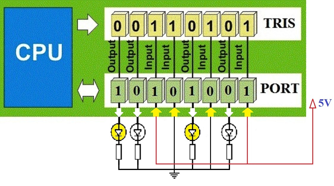
- TRIS is the command used for initializing the ports of the microcontroller. TRISB is an 8 bit register, in fact every word written in capital represents a register inside the microcontroller and you can get all the information about the register in the datasheet. Using this line will start the use of PORT B and if the value is ‘1’ in the respective register bit, that pin will be made input and if the value is ‘0’, the pin will be made output. One more thing, the use of ‘0x’ in that line represents that we are giving the data in hexadecimal number system. You can use ‘0b’ if you wish to give the data in binary and use nothing if you use decimal number system. So this line makes each 8 lines of port B output. Other way to give the same command is: TRISB=0; (decimal) and TRISB=0b00000000; (binary).
- PORTB is also a register like TRISB. This register passes the value out of port B. This means PORTB=0x00 will give low output from each eight line of port B. This is equivalent to clearing of port B at the start from any stray values. This line is not needed because there are no stray values at the start.
- Start of while loop. We write the entire program inside the while loop. After all initializations have been done, the main code is written here. This is done because this segment of program has to repeat over and over but the initializations do not need to be repeated. That is why the main program is written inside the while loop.
- PORTB is also a register like TRISB. This register passes the value out of port B. This means PORTB=0xff will give high output from each eight line of port B.
- This line is written to have a delay of 1000ms. So high logic will pass from port B pins for 500ms.
- This line will make the output from port B get down to 0V, ie logic ‘0’. It is to be considered that until the value in PORTB or any other port register is changed, the output from the corresponding port will also not change. So the output will drop from 5V (logic 1) to 0V (logic 0) only when this line is executed.
- Again a delay of 1000ms.
- End
So you can now understand why the LEDs connected to the port B will blink. For half a second, 5V or logic 1 is coming from port B and for the other half 0V or logic 0 is coming. See how easy it is to do anything using a microcontroller!
- Go to File-> New, write the program and save as a C file (*.c).
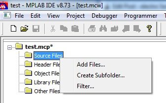
- Add this C file to Source group, Right Click on Source File >> Add Files
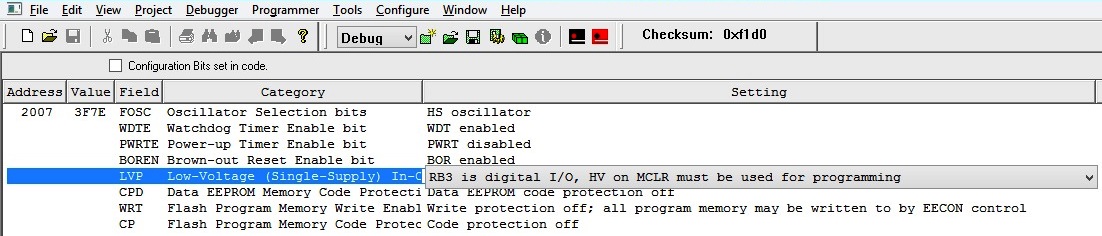
- Set the Configuration Bits using the Configuration bits tool. Click on Configure >> Configuration Bits
- Build the project to generate hex file. Click on Project >> Build

This was just a basic demonstration. In the same manner, there are registers for numerous operations in the microcontroller. You have to set the register and provide some command and it will be carried out. PIC 16F877A also has general purpose resisters and RAM so you can even use a lot of variables and constants. It supports floating point arithmetic and ASCII values also. Programming in Hi-Tech C is just like programming in any other C compiler with some additional commands.
Circuit Diagram
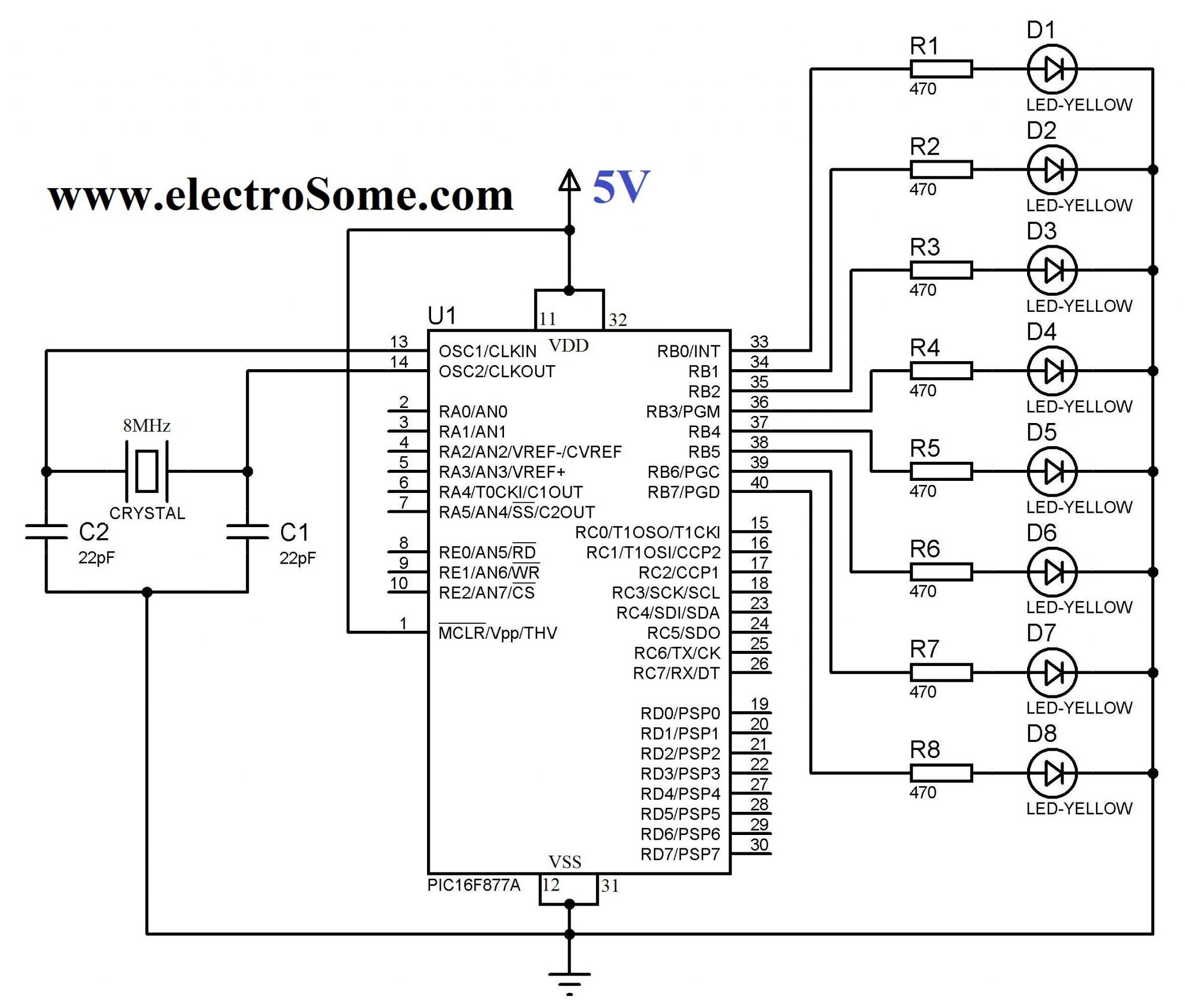
8MHz crystal is used to provide the required clock for the PIC 16F877A microcontroller. 22pF capacitors are used to stabilize the oscillation of the crystal. The first pin of the microcontroller (MCLR) is the Reset pin (stands for Memory Clear) which is tied to Vdd since it is an active low input. LEDs are connected to PORTB via 470Ω resistors to limit current through them.
You can simulate the working using Proteus. If you haven’t yet started with Proteus try this tutorial.
Video
Here is also a small video, which may help you.
Exporting Hex File
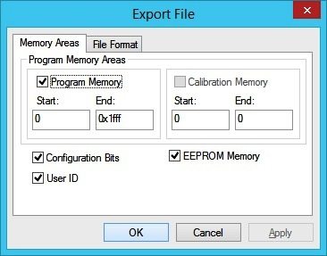
The above generated hex file doesn’t contain Configuration Bits, we should use the Export option in MPLAB to export the hex file with configuration bits.
- Click on File >> Export

- Click OK
- Give the file name and Click Save.
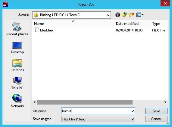
- Now burn this exported hex file to the microcontroller
Download Here
You can download Hi-Tech C files and Proteus files here…