Contents

This tutorial explains ” How to interface DC Motor with PIC Microcontroller ? “.
DC Motor and L293D
We can’t drive a DC Motor (depends) directly with a Microcontroller, as DC Motors requires high current and high voltage than a Microcontroller can handle. Microcontrollers usually operates at +5 or +3.3V supply and it I/O pin can provide only up to 25mA current. Commonly used DC Motors requires 12V supply and 300mA current, moreover interfacing DC Motors directly with Microcontrollers may affect the working of Microcontroller due to the Back EMF of the DC Motor. Thus it is clear that, it not a good idea to interface DC Motor directly with Microcontrollers.
The solution to above problems is to use H-bridge circuit.

It is a special circuit, by using the 4 switches we can control the direction of DC Motor. Depending upon our power requirements we can make our own H-bridge using Transistors/MOSFETs as switches. It is better to use ready made ICs, instead of making our own H-bridge.
L293D and L293 are two such ICs. These are dual H-bridge motor drivers, ie by using one IC we can control two DC Motors in both clock wise and counter clockwise directions. The L293D can provide bidirectional drive currents of up to 600-mA at voltages from 4.5 V to 36 V while L293 can provide up to 1A at same voltages. Both ICs are designed to drive inductive loads such as dc motors, bipolar stepping motors, relays and solenoids as well as other high-current or high-voltage loads in positive-supply applications. All inputs of these ICs are TTL compatible and output clamp diodes for inductive transient suppression are also provided internally. These diodes protect our circuit from the Back EMF of DC Motor.
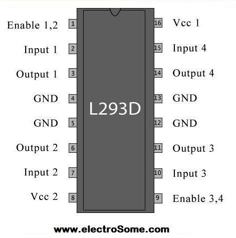
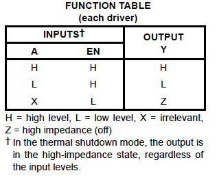
In both ICs, drivers are enabled in pairs, with drivers 1 and 2 are enabled by a high input to 1,2EN and drivers 3 and 4 are enabled by a high input to 3,4EN. When drivers are enabled, their outputs will be active and in phase with their inputs. When drivers are disabled, their outputs will be off and will be in the high-impedance state.
Interfacing with PIC Microcontroller
Circuit Diagram

Note: VDD and VSS of the pic microcontroller is not shown in the circuit diagram. VDD should be connected to +5V and VSS to GND.
We can drive two DC Motors with one L293D, in this example we are using only the first pair of drivers to drive one DC Motor. First pair of drivers are enabled by connecting EN1 to Logic HIGH. IN1 and IN2 are connected to RB0 and RB1 of PIC Microcontroller respectively which are used to provide control signal to the DC Motor. DC Motor is connected to OUT1 and OUT2 of the L293D.
MikroC Source Code
void main()
{
 TRISB = 0; // PORT B as output port
 PORTB = 1; // Set RB0 to high
 do
 {
   //To turn motor clockwise
   PORTB.F0 = 1;
   Delay_ms(2000);//2 seconds delay

   //To Stop motor
   PORTB = 0; // or PORTB = 3
   Delay_ms(2000);//2 seconds delay

   //To turn motor anticlockwise direction
   PORTB.F1 = 1;
   Delay_ms(2000);//2 seconds delay

   //To Stop motor
   PORTB = 0; // or PORTB = 3 (3 = 0b00000011)
   Delay_ms(2000); // 2 seconds delay

 }while(1);
}
Control Signals and Motor Status
| RB0/IN1 | RB2/IN2 | Motor Status |
|---|---|---|
| LOW | LOW | Stops |
| LOW | HIGH | Anti-Clockwise |
| HIGH | LOW | Clockwise |
| HIGH | HIGH | Stops |
Download Here
You can download MikroC Source Code, Proteus files etc here…