Contents
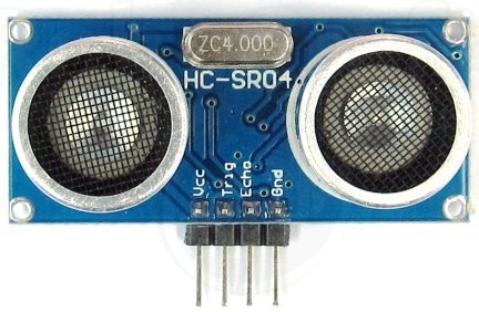
HC-SR04 Ultrasonic Distance Sensor is a popular and low cost solution for non-contact distance measurement function. It is able to measure distances from 2cm to 400cm with an accuracy of about 3mm. This module includes ultrasonic transmitter, ultrasonic receiver and its control circuit.
HC-SR04 module has 4 pins :
- VCC – 5V, +ive of the power supply
- TRIG – Trigger Pin
- ECHO – Echo Pin
- GND – -ive of the power supply
TRIG and ECHO pins can be used to interface this module with a microcontroller unit. These are TTL (0 – 5V) input output pins.
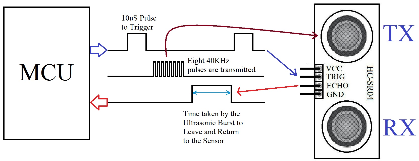
HC-SR04 Ultrasonic Module Working
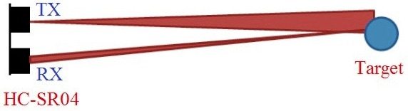
- Provide TRIGGER signal, atleast 10μS High Level (5V) pulse.
- The module will automatically transmit eight 40KHz ultrasonic burst.
- If there is an obstacle in-front of the module, it will reflect the ultrasonic burst.
- If the signal is back, ECHO output of the sensor will be in HIGH state (5V) for a duration of time taken for sending and receiving ultrasonic burst. Pulse width ranges from about 150μS to 25mS and if no obstacle is detected, the echo pulse width will be about 38ms.
Interfacing with PIC Microcontroller
Circuit Diagram
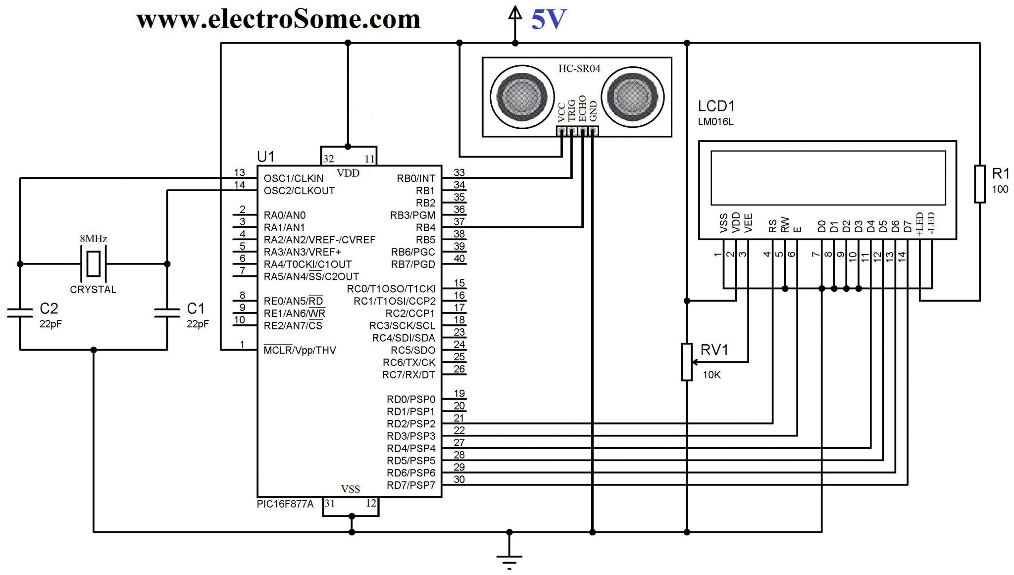
PIC 16F877A is the heart of this circuit. VDD and VSS of PIC Microcontroller is connected to +5V and GND respectively which will provide necessary power for its operation. A 8MHz crystal is connected to OSC1 and OSC2 pins of PIC, to provide clock for its operation. 22pF capacitors connected along with the crystal will stabilize the oscillations generated by the crystal. 16×2 LCD is connected to PORTD which is interfaced using 4 bit mode communication. 10KΩ preset is used to adjust the contrast of the LCD. A 100Ω resistor is used to limit current through the LCD back-light LED.
TRIGGER pin of HC-SR04 sensor is connected to RB0 (pin 33) of PIC which is to be configured as an Output PIN (TRIS bit is 0) and ECHO pin is connected to RB4 (pin 37) which is to be configured as an Input PIN (TRIS bit is 1).
Programming
Basic Steps :
- Provide TRIGGER to ultrasonic module
- Listen for Echo
- Start Timer when ECHO HIGH is received
- Stop Timer when ECHO goes LOW
- Read Timer Value
- Convert it to Distance
- Display it
Timer1 Module
Timer1 Module can be used as a 16 bit counter or timer. It consists of two 8 bit registers TMR1H and TMR1L which are readable and writable. The register pair, TMR1H:TMR1L increments from 0000H to FFFFH and rolls over to 0000H. If enabled Timer1 Overflow Interrupt is generated during rolls over to 0000H. Here we will use this module as a 16 bit Timer.
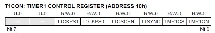
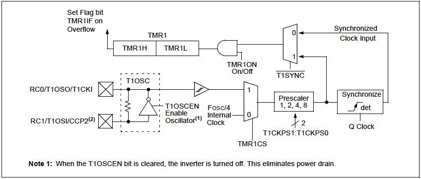
Since we are using Timer1 module as a Timer, we should use internal clock (Fosc/4), ie TMR1CS = 0. Prescaler is used to divide the internal clock (Fosc/4). Here we can set Prescaler as 2, ie T1CKPS1 = 0 & T1CKPS0 = 1. T1SYNC bit is ignored when TMR1CS = 0. As we are using internal clock (Fosc/4) we can disable oscillator, ie T1OSEN = 0. TMR1ON bit can be used to ON or OFF timer as per our requirements.
- Thus we can initialize timer as : T1CON = 0x10
- To TURN ON the Timer : T1CON.F0 = 1 or TMR1ON = 1
- To TURN OFF the Timer : T1CON.F0 = 0 or TMR1ON = 0
Fosc is the oscillator frequency, here we are using 8MHz crystal hence Fosc = 8MHz.
Time = (TMR1H:TMR1L)*(1/Internal Clock)*Prescaler
Internal Clock = Fosc/4 = 8MHz/4 = 2MHz
Therefore, Time = (TMR1H:TMR1L)*2/(2000000) = (TMR1H:TMR1L)/1000000
Distance Calculation
- Distance = Speed * Time
- Let d be the distance between Ultrasonic Sensor and Target
- Total distance traveled by the ultrasonic burst : 2d (forward and backward)
- Speed of Sound in Air : 340 m/s = 34000 cm/s
- Thus, d = (34000*Time)/2, where Time = (TMR1H:TMR1L)/(1000000)
- Therefore, d = (TMR1H:TMR1L)/58.82 cm
- TMR1H:TMR1L = TMR1L | (TMR1H<<8)
Simple Method – MikroC & MPLAB XC8 Program
MikroC Code
// LCD module connections
sbit LCD_RS at RD2_bit;
sbit LCD_EN at RD3_bit;
sbit LCD_D4 at RD4_bit;
sbit LCD_D5 at RD5_bit;
sbit LCD_D6 at RD6_bit;
sbit LCD_D7 at RD7_bit;

sbit LCD_RS_Direction at TRISD2_bit;
sbit LCD_EN_Direction at TRISD3_bit;
sbit LCD_D4_Direction at TRISD4_bit;
sbit LCD_D5_Direction at TRISD5_bit;
sbit LCD_D6_Direction at TRISD6_bit;
sbit LCD_D7_Direction at TRISD7_bit;
// End LCD module connections

void main()
{
  int a;
  char txt[7];
  Lcd_Init();
  Lcd_Cmd(_LCD_CLEAR);          // Clear display
  Lcd_Cmd(_LCD_CURSOR_OFF);     // Cursor off

  TRISB = 0b00010000;           //RB4 as Input PIN (ECHO)

  Lcd_Out(1,1,"Developed By");
  Lcd_Out(2,1,"electroSome");

  Delay_ms(3000);
  Lcd_Cmd(_LCD_CLEAR);

  T1CON = 0x10;                 //Initialize Timer Module

  while(1)
  {
    TMR1H = 0;                  //Sets the Initial Value of Timer
    TMR1L = 0;                  //Sets the Initial Value of Timer

    PORTB.F0 = 1;               //TRIGGER HIGH
    Delay_us(10);               //10uS Delay
    PORTB.F0 = 0;               //TRIGGER LOW

    while(!PORTB.F4);           //Waiting for Echo
    T1CON.F0 = 1;               //Timer Starts
    while(PORTB.F4);            //Waiting for Echo goes LOW
    T1CON.F0 = 0;               //Timer Stops

    a = (TMR1L | (TMR1H<<8));   //Reads Timer Value
    a = a/58.82;                //Converts Time to Distance
    a = a + 1;                  //Distance Calibration
    if(a>=2 && a<=400)          //Check whether the result is valid or not
    {
      IntToStr(a,txt);
      Ltrim(txt);
      Lcd_Cmd(_LCD_CLEAR);
      Lcd_Out(1,1,"Distance = ");
      Lcd_Out(1,12,txt);
      Lcd_Out(1,15,"cm");
    }
    else
    {
      Lcd_Cmd(_LCD_CLEAR);
      Lcd_Out(1,1,"Out of Range");
    }
    Delay_ms(400);
  }
}
MPLAB XC8 Code
#define _XTAL_FREQ 8000000

#define RS RD2
#define EN RD3
#define D4 RD4
#define D5 RD5
#define D6 RD6
#define D7 RD7

#include <xc.h>
#include "lcd.h";
#include <pic16f877a.h>

// BEGIN CONFIG
#pragma config FOSC = HS
#pragma config WDTE = OFF
#pragma config PWRTE = OFF
#pragma config BOREN = ON
#pragma config LVP = OFF
#pragma config CPD = OFF
#pragma config WRT = OFF
#pragma config CP = OFF
//END CONFIG
void main()
{
  int a;

  TRISB = 0b00010000;         //RB4 as Input PIN (ECHO)
  TRISD = 0x00;               // LCD Pins as Output

  Lcd_Init();

  Lcd_Set_Cursor(1,1);
  Lcd_Write_String("Developed By");
  Lcd_Set_Cursor(2,1);
  Lcd_Write_String("electroSome");

  __delay_ms(3000);
  Lcd_Clear();

  T1CON = 0x10;               //Initialize Timer Module

  while(1)
  {
    TMR1H = 0;                //Sets the Initial Value of Timer
    TMR1L = 0;                //Sets the Initial Value of Timer

    RB0 = 1;                  //TRIGGER HIGH
    __delay_us(10);           //10uS Delay
    RB0 = 0;                  //TRIGGER LOW

    while(!RB4);              //Waiting for Echo
    TMR1ON = 1;               //Timer Starts
    while(RB4);               //Waiting for Echo goes LOW
    TMR1ON = 0;               //Timer Stops

    a = (TMR1L | (TMR1H<<8)); //Reads Timer Value
    a = a/58.82;              //Converts Time to Distance
    a = a + 1;                //Distance Calibration
    if(a>=2 && a<=400)        //Check whether the result is valid or not
    {
      Lcd_Clear();
      Lcd_Set_Cursor(1,1);
      Lcd_Write_String("Distance = ");

      Lcd_Set_Cursor(1,14);
      Lcd_Write_Char(a%10 + 48);

      a = a/10;
      Lcd_Set_Cursor(1,13);
      Lcd_Write_Char(a%10 + 48);

      a = a/10;
      Lcd_Set_Cursor(1,12);
      Lcd_Write_Char(a%10 + 48);

      Lcd_Set_Cursor(1,15);
      Lcd_Write_String("cm");
    }
    else
    {
      Lcd_Clear();
      Lcd_Set_Cursor(1,1);
      Lcd_Write_String("Out of Range");
    }
    __delay_ms(400);
  }
}
This program uses our LCD Library for MPLAB XC8. You need to download and include the header file “lcd.h”. For more information please read the tutorial, Interfacing LCD with PIC Microcontroller – MPLAB XC8.
I hope that you can understand the working of the above program through comments. If you have any doubts, just comment below.
Distance Calibration
For accurate distance measuring you may calibrate the obtained result. Here for making the displayed distance more accurate, I added 1 to the the measured distance. This constant of calibration can be find using a series of practical experiments with a ruler scale.
In the above program there is a small problem as it infinitely waiting for ECHO and to ECHO goes LOW. If HIGH echo pulse is not received due to any reason, the program may get stuck there. So it is not a good practice to infinitely wait for ECHO and to ECHO goes LOW. The best solution is to use PORTB On-Change Interrupt feature of PIC Microcontroller.
PORTB On-Change Interrupt
Four pins of PORTB (RB4 – RB7) have interrupt on-change feature. Only those pins configured as INPUT PIN can cause this Interrupt while this interrupt is enabled. If the Logic State of any of these four pin changes (only Input Pins), interrupt will be generated.
PORTB On-Change Interrupt can be enabled by :
- Set Global Interrupt Enable bit : INTCON.GIE = 1
- Set PORTB On-Change Interrupt Enable Bit : INTCON.RBIE = 1
Note : PORTB On-Change Interrupt flag (INTCON.RBIF) will be set whenever this interrupt is generated and it should be cleared in software
Using Interrupt – MikroC & MPLAB XC8 Program
MikroC Code
// LCD module connections
sbit LCD_RS at RD2_bit;
sbit LCD_EN at RD3_bit;
sbit LCD_D4 at RD4_bit;
sbit LCD_D5 at RD5_bit;
sbit LCD_D6 at RD6_bit;
sbit LCD_D7 at RD7_bit;

sbit LCD_RS_Direction at TRISD2_bit;
sbit LCD_EN_Direction at TRISD3_bit;
sbit LCD_D4_Direction at TRISD4_bit;
sbit LCD_D5_Direction at TRISD5_bit;
sbit LCD_D6_Direction at TRISD6_bit;
sbit LCD_D7_Direction at TRISD7_bit;
// End LCD module connections

volatile int a;

//Interrupt function will be automatically executed on Interrupt
void interrupt()
{
  if(INTCON.RBIF == 1)                 //Makes sure that it is PORTB On-Change Interrupt
  {
    INTCON.RBIE = 0;                   //Disable On-Change Interrupt
    if(PORTB.F4 == 1)                  //If ECHO is HIGH
      T1CON.F0 = 1;                    //Start Timer
    if(PORTB.F4 == 0)                  //If ECHO is LOW
    {
      T1CON.F0 = 0;                    //Stop Timer
      a = (TMR1L | (TMR1H<<8))/58.82;  //Calculate Distance
    }
  }
  INTCON.RBIF = 0;                     //Clear PORTB On-Change Interrupt flag
  INTCON.RBIE = 1;                     //Enable PORTB On-Change Interrupt
}

void main()
{
  char txt[7];
  Lcd_Init();
  Lcd_Cmd(_LCD_CLEAR);                 // Clear display
  Lcd_Cmd(_LCD_CURSOR_OFF);            // Cursor off

  TRISB = 0b00010000;
  INTCON.GIE = 1;                      //Global Interrupt Enable
  INTCON.RBIF = 0;                     //Clear PORTB On-Change Interrupt Flag
  INTCON.RBIE = 1;                     //Enable PORTB On-Change Interrupt

  Lcd_Out(1,1,"Developed By");
  Lcd_Out(2,1,"electroSome");

  Delay_ms(3000);
  Lcd_Cmd(_LCD_CLEAR);

  T1CON = 0x10;                        //Initializing Timer Module

  while(1)
  {
    TMR1H = 0;                         //Setting Initial Value of Timer
    TMR1L = 0;                         //Setting Initial Value of Timer

    a = 0;

    PORTB.F0 = 1;                      //TRIGGER HIGH
    Delay_us(10);                      //10uS Delay
    PORTB.F0 = 0;                      //TRIGGER LOW

    Delay_ms(100);                     //Waiting for ECHO
    a = a + 1;                         //Error Correction Constant
    if(a>2 && a<400)                   //Check whether the result is valid or not
    {
      IntToStr(a,txt);
      Ltrim(txt);
      Lcd_Cmd(_LCD_CLEAR);
      Lcd_Out(1,1,"Distance = ");
      Lcd_Out(1,12,txt);
      Lcd_Out(1,15,"cm");
    }
    else
    {
      Lcd_Cmd(_LCD_CLEAR);
      Lcd_Out(1,1,"Out of Range");
    }
    Delay_ms(400);
  }
}
MPLAB XC8 Code
#define _XTAL_FREQ 8000000

#define RS RD2
#define EN RD3
#define D4 RD4
#define D5 RD5
#define D6 RD6
#define D7 RD7

#include <xc.h>
#include "lcd.h";
#include <pic16f877a.h>

// BEGIN CONFIG
#pragma config FOSC = HS
#pragma config WDTE = OFF
#pragma config PWRTE = OFF
#pragma config BOREN = ON
#pragma config LVP = OFF
#pragma config CPD = OFF
#pragma config WRT = OFF
#pragma config CP = OFF
//END CONFIG

volatile int a;

void interrupt echo()
{
  if(RBIF == 1)                       //Makes sure that it is PORTB On-Change Interrupt
  {
    RBIE = 0;                         //Disable On-Change Interrupt
    if(RB4 == 1)                      //If ECHO is HIGH
    TMR1ON = 1;                       //Start Timer
    if(RB4 == 0)                      //If ECHO is LOW
    {
      TMR1ON = 0;                     //Stop Timer
      a = (TMR1L | (TMR1H<<8))/58.82; //Calculate Distance
    }
  }
  RBIF = 0;                           //Clear PORTB On-Change Interrupt flag
  RBIE = 1;                           //Enable PORTB On-Change Interrupt
}
void main()
{
  TRISB = 0b00010000;                 //RB4 as Input PIN (ECHO)
  TRISD = 0x00;                       // LCD Pins as Output
  GIE = 1;                            //Global Interrupt Enable
  RBIF = 0;                           //Clear PORTB On-Change Interrupt Flag
  RBIE = 1;                           //Enable PORTB On-Change Interrupt

  Lcd_Init();

  Lcd_Set_Cursor(1,1);
  Lcd_Write_String("Developed By");
  Lcd_Set_Cursor(2,1);
  Lcd_Write_String("electroSome");

  __delay_ms(3000);
  Lcd_Clear();

  T1CON = 0x10;                       //Initialize Timer Module

  while(1)
  {
    TMR1H = 0;                        //Sets the Initial Value of Timer
    TMR1L = 0;                        //Sets the Initial Value of Timer

    RB0 = 1;                          //TRIGGER HIGH
    __delay_us(10);                   //10uS Delay
    RB0 = 0;                          //TRIGGER LOW

    __delay_ms(100);                  //Waiting for ECHO
    a = a + 1;                        //Error Correction Constant

    if(a>=2 && a<=400)                //Check whether the result is valid or not
    {
      Lcd_Clear();
      Lcd_Set_Cursor(1,1);
      Lcd_Write_String("Distance = ");

      Lcd_Set_Cursor(1,14);
      Lcd_Write_Char(a%10 + 48);

      a = a/10;
      Lcd_Set_Cursor(1,13);
      Lcd_Write_Char(a%10 + 48);

      a = a/10;
      Lcd_Set_Cursor(1,12);
      Lcd_Write_Char(a%10 + 48);

      Lcd_Set_Cursor(1,15);
      Lcd_Write_String("cm");
    }
    else
    {
      Lcd_Clear();
      Lcd_Set_Cursor(1,1);
      Lcd_Write_String("Out of Range");
    }
    __delay_ms(400);
  }
}
This program uses our LCD Library for MPLAB XC8. You need to download and include the header file “lcd.h”. For more information please read the tutorial, Interfacing LCD with PIC Microcontroller – MPLAB XC8.
Download
You can download entire project files here.
- Interfacing HC-SR04 with PIC Microcontroller – MikroC Pro
- Interfacing HC-SR04 with PIC Microcontroller – MPLAB XC8
Want to See the Output ?
