
Contents
I2C or IIC or I2C stands for Inter-Integrated Circuit. It is a very popular multi-master, multi-slave serial communication interface developed by Philips. I2C uses two bidirectional open drain data lines, Serial Data (SDA) and Serial Clock (SCL) with pull up resistors as shown below. Unlike UART, you can connect and communicate to multiple devices using the same I2C bus.
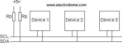
I2C is a master slave protocol. It means that devices connected to I2C bus will be either master or slave. The master is the device which initiate communication and it drives clock (SCL) line. Slaves are the devices which responds to master and it cannot initiate a communication. An I2C bus can have multiple masters and multiple slaves. But commonly we are using single master and multiple slaves. Each slaves are identified or addressed by a unique address. The master will send address of slave + R/W bit first, then followed by other data. So the slave with that particular address will be activated at that moment. R/W bit indicates whether the master wants to read data from or write data to the slave. For example, we can have a microcontroller or host device which is connected to different slave devices like I/O Port Expanders, LED/LCD Drivers, ADCs, DACs, EEPROMs, Real Time Clock (RTC) etc.
Most of the PIC microcontrollers have built in Master Synchronous Serial Port (MSSP) module which can be configured to operate in following modes.
- Serial Peripheral Interface (SPI)
- Inter-Integrated Circuit (I2C) – Slave, Master & Multi-master modes
In this tutorial we will learn how to operate MSSP module of PIC Microcontroller as I2C master or slave. For demonstration we are using PIC 16F877A microcontroller. You can easily convert it for other microcontrollers if you understand it clearly.
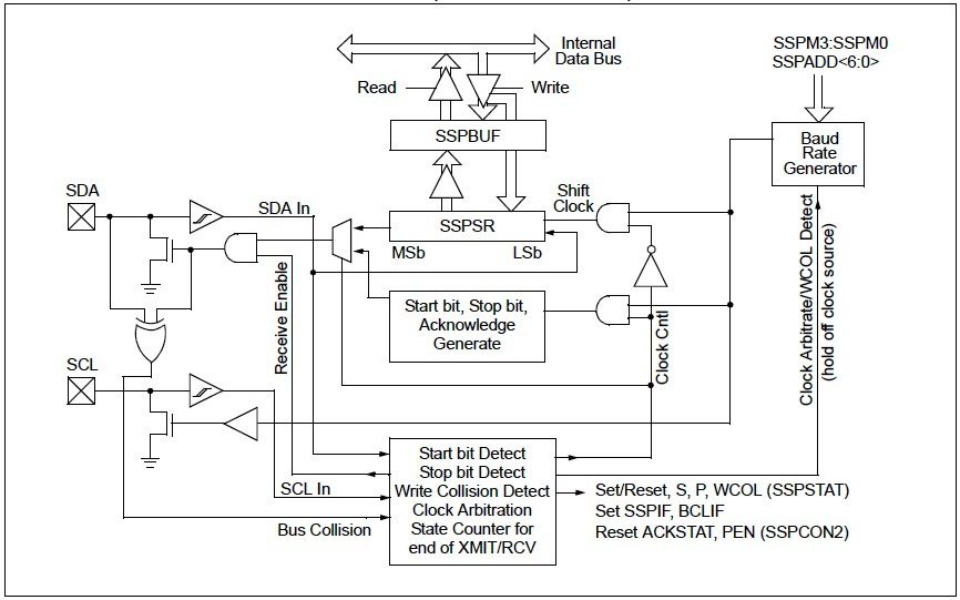
MSSP Module in I2C Mode
Let’s see in detail about working of MSSP module of PIC Microcontroller in I²C mode. MSSP module can be configured to operate in both 10 bit and 7 bit address mode. In this example we are demonstrating 7 bit mode only as it is the commonly used one. You can easily modify the program to work in 10 bit mode.
I2C Master
We need to write to SSPCON1 and SSPADD registers to configure MSSP module as I²C Master and to set the clock frequency of I²C communication respectively.
I2C Slave
Similar to above, we need to write to SSPCON1 and SSPADD registers to configure MSSP module in I²C slave mode and to set the slave device address respectively.
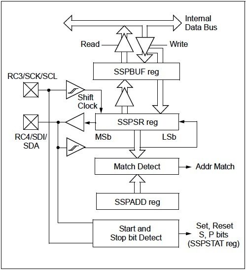
Clock generated by the master on SCL line will cause the data to shift in and shift out of the SSPSR register which makes the I2C communication happen.
I2C Registers
SSPSTAT – MSSP Status Register
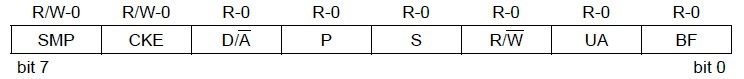
- Bit 0 BF : This is the Buffer Full status bit. In the transmit mode this bit will set when we write data to SSPBUF register and it is cleared when the data is shifted out. In the receive mode this bit will set when the data or address is received in the SSPBUF register and it is cleared when we reads the SSPBUF register.
- Bit 1 UA : This is the Update Address bit and is used only in 10 bit address mode. It indicates that user needs to update the address in the SSPADD register.
- Bit 2 R/W : This is the Read/Write bit information. In the slave mode it indicates the status of R/W bit during the last address match. In the master mode, 1 indicates that transmit is in progress and vice versa.
- Bit 3 S : This bit indicates that a Start bit is detected last and it will automatically cleared during Reset.
- Bit 4 P : As above, this bit indicates that a Stop bit is detected last and it will automatically cleared during Reset.
- Bit 5 D/A : This is the data or address indicator bit and it is used only in slave mode. If it is set, the last byte received was data otherwise it will be address.
- Bit 6 CKE : Setting this bit enables SMBus specific inputs. SMBus is an another bus similar to I2C, which are compatible each other.
- Bit 7 SMP : Setting this bit disables slew rate control and vice versa.
SSPCON1 – MSSP Control Register 1
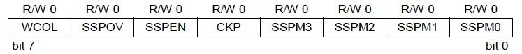
- Bit 0 ~ 3 SSPM0 ~ SSPM3 : These are synchronous serial port mode select bits.

- Bit 4 CKP : This is SCL clock release control bit. It is used only in slave mode. Setting this bit releases the clock. If zero, it holds the clock (clock stretch).
- Bit 5 : SSPEN : This is the synchronous serial port enable bit. Setting this bit enables the serial port.
- Bit 6 : SSPOV : This is receive over flow indicator bit. If this bit is set during receive mode, it indicates that a byte is received while SSPBUF is holding the previous value. And it has no application in transmit mode. We must clear this bit in software.
- Bit 7 WCOL : It is the write collision detect bit. If this bit is set during master transmit mode, it indicates that a write to SSPBUF register was attempted when I2C conditions was not valid for a transmission to be started. And if it is set during a slave transmit mode, it indicates that SSPBUF register is written when it is transmitting the previous word. We must clear this bit in software.
SSPCON2 – MSSP Control Register 2
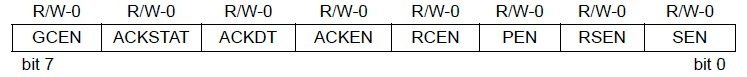
- Bit 0 SEN : Start Condition or Stretch Enable bit. In master mode, setting this bit initiate start condition on SCL & SDA pins and it will be automatically cleared by the hardware. And in slave mode setting this bit enables clock stretching for both slave receive and slave transmit. If it is cleared in slave mode, clock stretching is enabled only for slave transmit.
- Bit 1 RSEN : Repeated start condition enable bit. This bit has application only in master mode. Setting this bit will initiate repeated start condition on both SCL & SDA pins and it will automatically cleared in hardware.
- Bit 2 PEN : Stop condition enable bit. This bit has application only in master mode. Setting this bit will initiate stop condition on both SCL & SDA pins and it will be automatically cleared in hardware.
- Bit 3 RCEN : Receive enable bit. This bit also has application only in master mode. Setting this bit enables receive mode for I2C.
- Bit 4 ACKEN : Acknowledge sequence enable bit. Setting this bit initiates acknowledge sequence on SCL & SDA lines and it will send ACKDT (see below) bit. This bit will be automatically cleared in hardware. It has application only in master receive mode.
- Bit 5 ACKDT : Acknowledge data bit. 1 means not acknowledge and 0 means acknowledge. This value will be transmitted when we set the ACKEN bit (above). This bit has application only in master receive mode.
- Bit 6 ACKSTAT : Acknowledge status bit. 1 indicates that acknowledge was not received from the slave and vice versa. This bit has application in master transmit mode only.
- Bit 7 GCEN : General call enable bit. Setting this bit enables interrupt when a general call address is received in the register SSPSR.
I2C Library for MPLAB XC8
Master Functions
Initialize I2C Module as Master
void I2C_Master_Init(const unsigned long c)
{
  SSPCON = 0b00101000;            //SSP Module as Master
  SSPCON2 = 0;
  SSPADD = (_XTAL_FREQ/(4*c))-1; //Setting Clock Speed
  SSPSTAT = 0;
  TRISC3 = 1;                   //Setting as input as given in datasheet
  TRISC4 = 1;                   //Setting as input as given in datasheet
}
For Waiting
void I2C_Master_Wait()
{
  while ((SSPSTAT & 0x04) || (SSPCON2 & 0x1F)); //Transmit is in progress
}
Start Condition
void I2C_Master_Start()
{
  I2C_Master_Wait();
  SEN = 1;             //Initiate start condition
}
Repeated Start
void I2C_Master_RepeatedStart()
{
  I2C_Master_Wait();
  RSEN = 1;           //Initiate repeated start condition
}
Stop Condition
void I2C_Master_Stop()
{
  I2C_Master_Wait();
  PEN = 1;           //Initiate stop condition
}
Write Data
void I2C_Master_Write(unsigned d)
{
  I2C_Master_Wait();
  SSPBUF = d;         //Write data to SSPBUF
}
Read Data
unsigned short I2C_Master_Read(unsigned short a)
{
  unsigned short temp;
  I2C_Master_Wait();
  RCEN = 1;
  I2C_Master_Wait();
  temp = SSPBUF;      //Read data from SSPBUF
  I2C_Master_Wait();
  ACKDT = (a)?0:1;    //Acknowledge bit
  ACKEN = 1;          //Acknowledge sequence
  return temp;
}
Slave Functions
Initialize module as slave
void I2C_Slave_Init(short address)
{
  SSPSTAT = 0x80;
  SSPADD = address; //Setting address
  SSPCON = 0x36;    //As a slave device
  SSPCON2 = 0x01;
  TRISC3 = 1;       //Setting as input as given in datasheet
  TRISC4 = 1;       //Setting as input as given in datasheet
  GIE = 1;          //Global interrupt enable
  PEIE = 1;         //Peripheral interrupt enable
  SSPIF = 0;        //Clear interrupt flag
  SSPIE = 1;        //Synchronous serial port interrupt enable
}
On Receive interrupt
Note : This is not a general function, so you need to modify it according to your application.
void interrupt I2C_Slave_Read()
{
  if(SSPIF == 1)
  {
    SSPCONbits.CKP = 0;

    if ((SSPCONbits.SSPOV) || (SSPCONbits.WCOL)) //If overflow or collision
    {
      z = SSPBUF; // Read the previous value to clear the buffer
      SSPCONbits.SSPOV = 0; // Clear the overflow flag
      SSPCONbits.WCOL = 0; // Clear the collision bit
      SSPCONbits.CKP = 1;
    }

  if(!SSPSTATbits.D_nA && !SSPSTATbits.R_nW) //If last byte was Address + Write
  {
    z = SSPBUF;
    while(!BF);
    PORTD = SSPBUF;
    SSPCONbits.CKP = 1;
  }
  else if(!SSPSTATbits.D_nA && SSPSTATbits.R_nW) //If last byte was Address + Read
  {
    z = SSPBUF;
    BF = 0;
    SSPBUF = PORTB ;
    SSPCONbits.CKP = 1;
    while(SSPSTATbits.BF);
  }

  SSPIF = 0;
  }
}
PIC to PIC Communication using I2C
In this example we have bidirectional communication between two pic microcontrollers. 8 bit switches and 8 LEDs are connected to each microcontroller. We will be controlling LEDs connected to a PIC with switches connected to other microcontroller.
Circuit Diagram
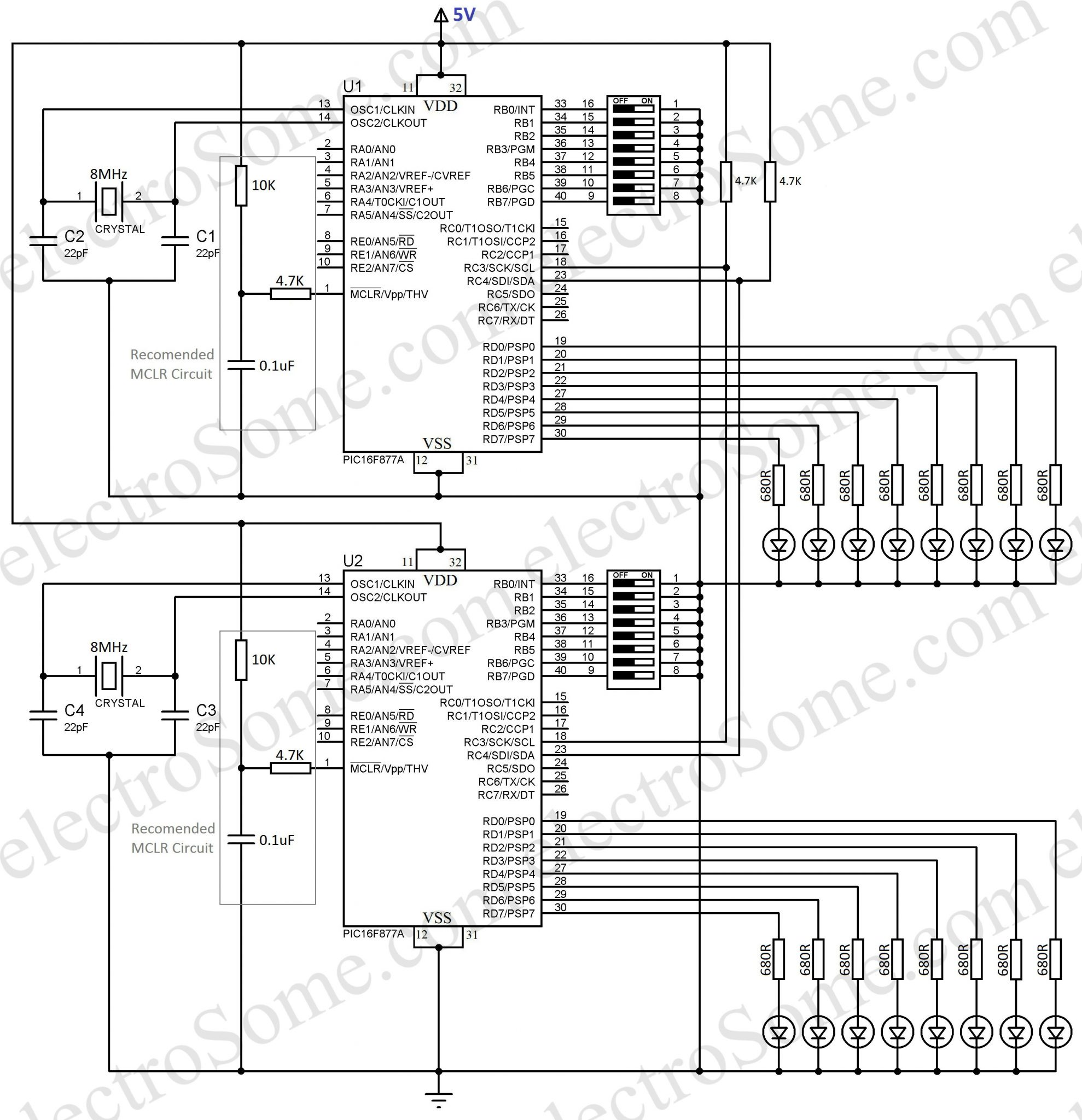
Hope you can easily understand above circuit diagram. You can make any of above 2 microcontroller as master, it depends only on the program written on it. 8MHz crystals are used for providing required clock for the operation of microcontrollers. An RCR (Resistor-Capacitor-Resistor) made using 10KΩ, 0.1µF, 4.7KΩ is connected to MCLR pin of PIC Microcontroller as recommended by Microchip. It will work fine even if you tie MCLR pin directly to VDD but Microchip doesn’t recommends it. 680Ω resistors are used to limit current through LEDs which are connected to PORTD of PIC microcontroller. 8 bit dip switches are connected to the PORTB of PIC microcontroller. Here we are using Internal Pull Up of PORTB. Hence no external resistors are required for switches.
MPLAB XC8 – Code
Since circuit of both microcontrollers are identical, you can use any of the 2 microcontrollers are master or slave.
Master
// PIC16F877A Configuration Bit Settings
// 'C' source line config statements
#include <xc.h>
#include <pic16f877a.h>

#define _XTAL_FREQ 8000000

// #pragma config statements should precede project file includes.
// Use project enums instead of #define for ON and OFF.

// CONFIG
#pragma config FOSC = XT   // Oscillator Selection bits (XT oscillator)
#pragma config WDTE = OFF  // Watchdog Timer Enable bit (WDT disabled)
#pragma config PWRTE = OFF // Power-up Timer Enable bit (PWRT disabled)
#pragma config BOREN = OFF // Brown-out Reset Enable bit (BOR disabled)
#pragma config LVP = OFF   // Low-Voltage In-Circuit Serial Programming Enable bit
#pragma config CPD = OFF   // Data EEPROM Memory Code Protection bit
#pragma config WRT = OFF   // Flash Program Memory Write Enable bits
#pragma config CP = OFF    // Flash Program Memory Code Protection bit

void I2C_Master_Init(const unsigned long c)
{
  SSPCON = 0b00101000;
  SSPCON2 = 0;
  SSPADD = (_XTAL_FREQ/(4*c))-1;
  SSPSTAT = 0;
  TRISC3 = 1;        //Setting as input as given in datasheet
  TRISC4 = 1;        //Setting as input as given in datasheet
}

void I2C_Master_Wait()
{
  while ((SSPSTAT & 0x04) || (SSPCON2 & 0x1F));
}

void I2C_Master_Start()
{
  I2C_Master_Wait();
  SEN = 1;
}

void I2C_Master_RepeatedStart()
{
  I2C_Master_Wait();
  RSEN = 1;
}

void I2C_Master_Stop()
{
  I2C_Master_Wait();
  PEN = 1;
}

void I2C_Master_Write(unsigned d)
{
  I2C_Master_Wait();
  SSPBUF = d;
}

unsigned short I2C_Master_Read(unsigned short a)
{
  unsigned short temp;
  I2C_Master_Wait();
  RCEN = 1;
  I2C_Master_Wait();
  temp = SSPBUF;
  I2C_Master_Wait();
  ACKDT = (a)?0:1;
  ACKEN = 1;
  return temp;
}

void main()
{
  nRBPU = 0;                    //Enable PORTB internal pull up resistor
  TRISB = 0xFF;                 //PORTB as input
  TRISD = 0x00;                 //PORTD as output
  PORTD = 0x00;                 //All LEDs OFF
  I2C_Master_Init(100000);      //Initialize I2C Master with 100KHz clock
  while(1)
  {
    I2C_Master_Start();         //Start condition
    I2C_Master_Write(0x30);     //7 bit address + Write
    I2C_Master_Write(PORTB);    //Write data
    I2C_Master_Stop();          //Stop condition
    __delay_ms(200);
    I2C_Master_Start();         //Start condition
    I2C_Master_Write(0x31);     //7 bit address + Read
    PORTD = I2C_Master_Read(0); //Read + Acknowledge
    I2C_Master_Stop();          //Stop condition
    __delay_ms(200);
  }
}
Slave
// PIC16F877A Configuration Bit Settings
// 'C' source line config statements

#include <xc.h>
#include <pic16f877a.h>
#define _XTAL_FREQ 8000000

// #pragma config statements should precede project file includes.
// Use project enums instead of #define for ON and OFF.

// CONFIG
#pragma config FOSC = XT    // Oscillator Selection bits (XT oscillator)
#pragma config WDTE = OFF   // Watchdog Timer Enable bit (WDT disabled)
#pragma config PWRTE = OFF  // Power-up Timer Enable bit (PWRT disabled)
#pragma config BOREN = OFF  // Brown-out Reset Enable bit (BOR disabled)
#pragma config LVP = OFF    // Low-Voltage In-Circuit Serial Programming Enable bit
#pragma config CPD = OFF    // Data EEPROM Memory Code Protection bit
#pragma config WRT = OFF    // Flash Program Memory Write Enable bits
#pragma config CP = OFF     // Flash Program Memory Code Protection bit
short z;
void interrupt I2C_Slave_Read()
{
  if(SSPIF == 1)
  {
    SSPCONbits.CKP = 0;

    if ((SSPCONbits.SSPOV) || (SSPCONbits.WCOL))
    {
      z = SSPBUF; // Read the previous value to clear the buffer
      SSPCONbits.SSPOV = 0; // Clear the overflow flag
      SSPCONbits.WCOL = 0;  // Clear the collision bit
      SSPCONbits.CKP = 1;
    }

    if(!SSPSTATbits.D_nA && !SSPSTATbits.R_nW)
    {
      z = SSPBUF;
      while(!BF);
      PORTD = SSPBUF;
      SSPCONbits.CKP = 1;
    }
    else if(!SSPSTATbits.D_nA && SSPSTATbits.R_nW)
    {
      z = SSPBUF;
      BF = 0;
      SSPBUF = PORTB ;
      SSPCONbits.CKP = 1;
      while(SSPSTATbits.BF);
    }

    SSPIF = 0;
  }
}

void I2C_Slave_Init(short address)
{
  SSPSTAT = 0x80;
  SSPADD = address;
  SSPCON = 0x36;
  SSPCON2 = 0x01;
  TRISC3 = 1;   //Setting as input as given in datasheet
  TRISC4 = 1;   //Setting as input as given in datasheet
  GIE = 1;
  PEIE = 1;
  SSPIF = 0;
  SSPIE = 1;
}

void main()
{
  nRBPU = 0;            //Enables PORTB internal pull up resistors
  TRISB = 0xFF;         //PORTB as input
  TRISD = 0x00;         //PORTD as output
  PORTD = 0x00;         //All LEDs OFF
  I2C_Slave_Init(0x30); //Initialize as a I2C Slave with address 0x30
  while(1);
}
I hope that you understand above programs. Please do comment if you have any doubts.
Download Here
You can download the complete MPLAB program and Proteus simulation files here.