Contents
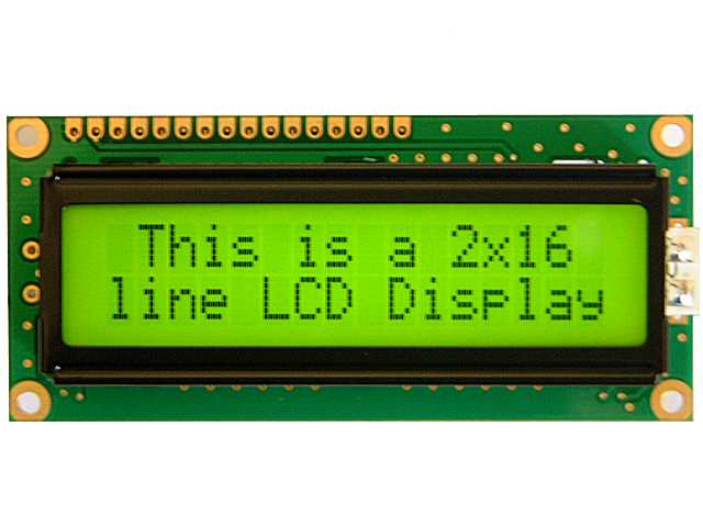
Liquid Crystal Display (LCD) is very commonly used electronic display module and having a wide range of applications such as calculators, laptops, mobile phones etc. 16×2 character lcd display is very basic module which is commonly used in electronics devices and projects. It can display 2 lines of 16 characters. Each character is displayed using 5×7 or 5×10 pixel matrix.
Interfacing 16×2 LCD with 8051 using Keil C is bit complex because there is no powerful libraries in Keil C. To solve this problem we have developed a LCD library which includes commonly used features, you just need to include our header file and use it. You can download the header file at the bottom of this article.
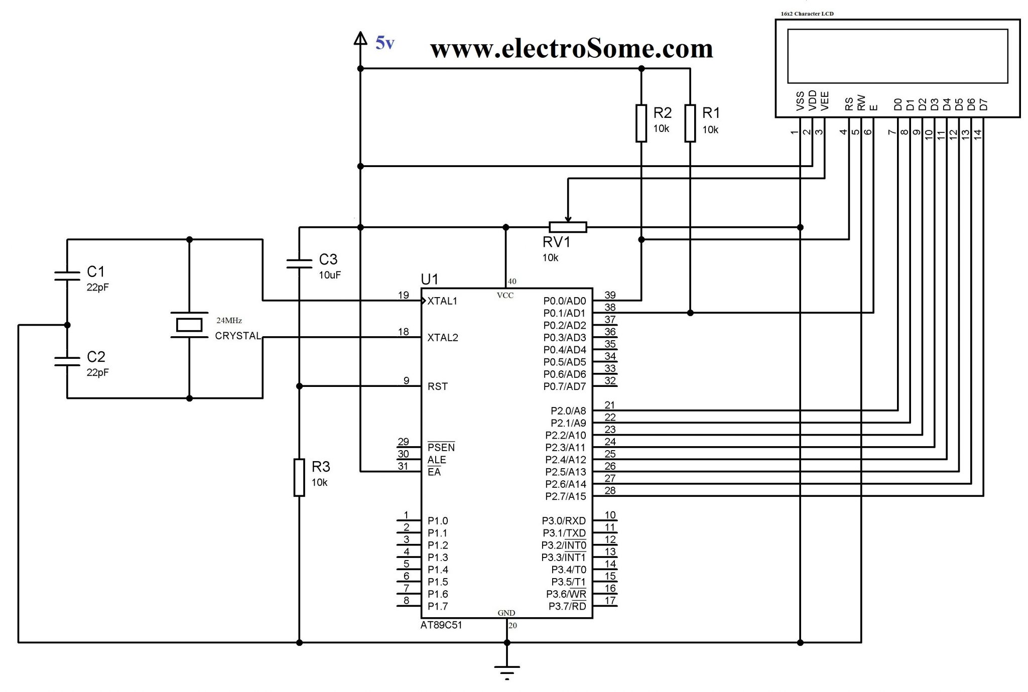
LCD can be interfaced with microcontroller in 4 Bit or 8 Bit mode. These differs in how data is send to LCD. In 8 bit mode to write a character, 8 bit ASCII data is send through the data lines D0 – D7 and data strobe is given through E of the LCD. LCD commands which are also 8 bit are written to LCD in similar way.
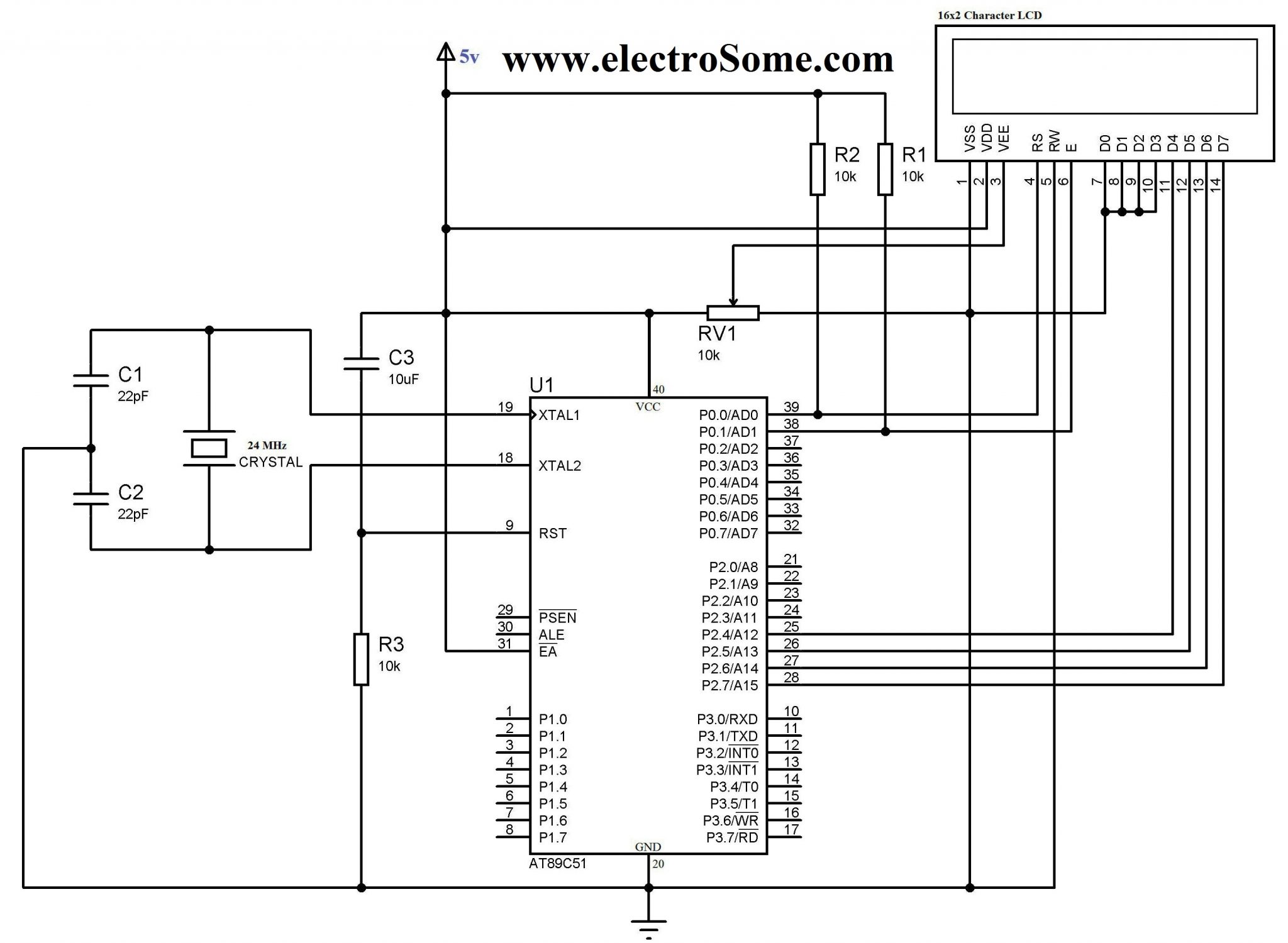
But 4 Bit Mode uses only 4 data lines D4 – D7. In this mode 8 bit character ASCII data and command data are divided into two parts and send sequentially through data lines. The idea of 4 bit communication is used save pins of microcontroller. 4 bit communication is a bit slower than 8 bit communication but this speed difference can be neglected since LCDs are slow speed devices. Thus 4 bit mode data transfer is most commonly used.
Library Functions in lcd.h
Lcd8_Init() & Lcd4_Init() : These function will initialize the LCD module which is connnected to pins defined by following bit addressable variables.
For 8 Bit Mode:
//LCD Module Connections
sbit RS = P0^0;
sbit EN = P0^1;
sbit D0 = P2^0;
sbit D1 = P2^1;
sbit D2 = P2^2;
sbit D3 = P2^3;
sbit D4 = P2^4;
sbit D5 = P2^5;
sbit D6 = P2^6;
sbit D7 = P2^7;
//End LCD Module Connections
For 4 Bit Mode :
//LCD Module Connections
sbit RS = P0^0;
sbit EN = P0^1;
sbit D4 = P2^4;
sbit D5 = P2^5;
sbit D6 = P2^6;
sbit D7 = P2^7;
//End LCD Module Connections
These connections must be defined for the proper working of the LCD library.
Lcd8_Clear() & Lcd4_Clear() : These functions will clear the LCD screen when interfaced with 8051 in 8 bit and 4 bit mode respectively.
Lcd8_Set_Cursor() & Lcd4_Set_Cursor() : These functions are used to set the cursor position on the lcd screen. By using this function we can change the position of character and string displayed by the following functions.
Lcd8_Write_Char() & Lcd4_Write_Char() : These functions are used to write a character to the LCD screen.
Lcd8_Write_String() & Lcd8_Write_String() : These functions are used to write a string or text to the LCD screen.
Lcd8_Shift_Left() & Lcd4_Shift_Left() : These functions are used to shift display left without changing the data in display RAM.
Lcd8_Shift_Right() & Lcd8_Shift_Right() : These functions are used to shift display right without changing the data in display RAM.
8 Bit Mode LCD Interfacing
Circuit Diagram
Keil C Code
#include<reg52.h> //including sfr registers for ports of the controller
#include<lcd.h> // Can be download from bottom of this article

//LCD Module Connections
sbit RS = P0^0;
sbit EN = P0^1;
sbit D0 = P2^0;
sbit D1 = P2^1;
sbit D2 = P2^2;
sbit D3 = P2^3;
sbit D4 = P2^4;
sbit D5 = P2^5;
sbit D6 = P2^6;
sbit D7 = P2^7;
//End LCD Module Connections
void Delay(int a)
{
  int j;
  int i;
  for(i=0;i<a;i++)
  {
    for(j=0;j<100;j++)
    {
    }
  }
}
void main()
{
  int i;
  Lcd8_Init();
  while(1)
  {
    Lcd8_Set_Cursor(1,1);
    Lcd8_Write_String("electroSome LCD Hello World");
    for(i=0;i<15;i++)
    {
      Delay(1000);
      Lcd8_Shift_Left();
    }
    for(i=0;i<15;i++)
    {
      Delay(1000);
      Lcd8_Shift_Right();
    }
    Lcd8_Clear();
    Lcd8_Write_Char('e');
    Lcd8_Write_Char('S');
    Delay(3000);
  }
}
4 Bit Mode LCD Interfacing
Circuit Diagram
Keil C Code
#include<reg52.h> //including sfr registers for ports of the controller
#include<lcd.h> //Can be download from bottom of this article

//LCD Module Connections
sbit RS = P0^0;
sbit EN = P0^1;
sbit D4 = P2^4;
sbit D5 = P2^5;
sbit D6 = P2^6;
sbit D7 = P2^7;
//End LCD Module Connections
void Delay(int a)
{
  int j;
  int i;
  for(i=0;i<a;i++)
  {
    for(j=0;j<100;j++)
    {
    }
  }
}
void main()
{
  int i;
  Lcd4_Init();
  while(1)
  {
    Lcd4_Set_Cursor(1,1);
    Lcd4_Write_String("electroSome LCD Hello World");
    for(i=0;i<15;i++)
    {
      Delay(1000);
      Lcd4_Shift_Left();
    }
    for(i=0;i<15;i++)
    {
      Delay(1000);
      Lcd4_Shift_Right();
    }
    Lcd4_Clear();
    Lcd4_Set_Cursor(2,1);
    Lcd4_Write_Char('e');
    Lcd4_Write_Char('S');
    Delay(2000);
  }
}
How to use the Header File ?
Copy and Paste the header file lcd.h to your project folder. Then add lcd.h to your source group.
1. Right Click on Source Group
2. Click on “Add Files to ‘Group Source Group 1’
3. Select lcd.h and Click Add
Optimize Code for more Efficiency
You already seen that by using our header file lcd.h you can connect LCD to any of the output pins of the microcontroller. For this more coding is required in the header file which makes the generated hex file less efficient and large in size. You can solve this problem by making some changes in the header file according to your hardware connections. For eg : in the above sample programs I have used port P2 for sending data and command. Just replace the functions Lcd4_Port(data) and Lcd8_Port(data) with P2 = data.
Download Here
You can download header file, keil c files, proteus files etc here…