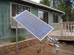
We all know that a Solar Panel can be used to convert light energy to electrical energy. The amount of converted energy depends on the amount of light falling on the Panel. Generally Solar Panels are stationary devices which is fixed at a position. The produced electrical energy can be increased if we move the solar panel as the movement of the Sun. Here is a simple low cost Solar Tracker circuit which automatically moves the solar panel in the direction of Sun. The movement of the Sun is detected using two LDRs which are arranged on the Solar Panel in such a way that the intensity of light falling on it varies as the direction of Sun changes.
Circuit Diagram
Working
The heart of the above circuit is two voltage comparators made using LM358 Dual Op-Amp. We all know that when the intensity of light falling on a LDR increases, its resistance decreases. Here LDR is connected with a series resistor (R3 & R4), hence when the intensity of light falling on a LDR increases, voltage across corresponding resistor (R3 or R4) increases.
The output of the voltage comparator will be high when the voltage at non-inverting terminal (+) is higher than the voltage at the inverting terminal (-). Inverting (-) terminals of both comparators are shorted and connected to a variable resistor (RV1), which is used to set the reference voltage. Thus the sensitivity of both LDRs can be adjusted by varying the 10K pot shown on the left side of the circuit diagram. When the light falls on a LDR increases, voltage at the non-inverting (+) terminal of corresponding comparator increases and its output goes HIGH.
The direction of motor rotation is controlled by the H-Bridge formed by the complimentary symmetry transistors BC547 and BC557. Consider the case when the output of first comparator (U1:A) is high and output of second comparator (U1:B) is low. In this case transistors Q1 and Q4 will turns on and the resulting current rotates the motor in clockwise direction. Consider the case when the output of the first comparator is low and the output of the second comparator is high. In this case transistors Q2 and Q3 will turns on and the resultant current rotates the motor in anticlockwise direction. If the output of both comparators are low, transistors Q3 and Q4 turns on, but no current will flow through the motor. Similarly if the output of both comparators are high, transistors Q1 and Q2 turns on, but no current will flow through the motor.
The DC Motor should be connected to the panel in such a way that, the rotation of motor rotates the panel in the direction of movement of the Sun.
