Contents
I already posted about transformerless power supplies in the article, Transformerless DC Power Supply. Here we will see how to design a capacitor dropper power supply. Capacitor power supplies are simple, low cost and light weight solution for providing dc supplies to circuits which require low currents. It is low cost and light weight since there is no bulky transformers.
Circuit Diagram
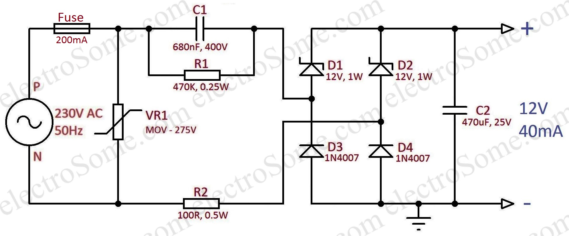
The 200mA fuse will protect the circuit from mains during shot circuit or component failures. The 275V MOV (Metal Oxide Varistor) will protect from power supply spikes or surges. The X Rated Capacitor C1 is the core part of this power supply as it will drop the excess mains voltage across it. The excess energy will not dissipated as heat as we are using capacitor dropper instead of resistor. The resistor R1 is the bleeder resistor for capacitor C1. Which will discharge the capacitor when the supply is switch off, so it will prevent any shocks due to capacitor charge. Resistor R2 is provided to prevent excess transient current that can flow when the power supply is switch on.
Diodes D1 ~ D4 constitutes a bridge rectifier which will rectify the input ac power. Among these D1 & D2 are zener diodes. So the rectified output will gets clipped at its zener voltage. Capacitor C2 is the filtering capacitor which will filter the rectified ac voltage.
Working
Working is self explanatory in the above animation. In the positive half cycle diodes D1 & D4 gets forward biased and current flows through the load. Output voltage will be clipped by the zener effect for diode D1. In the negative half cycle diodes D2 & D3 gets forward biased and the output voltage will get clipped by the zener effect of diode D2.
Design
Maximum Current
Current I = V/Z, where V is the voltage and Z is the impedance.
Capacitive Reactance XC1 = 1/(2πfC), where f is the frequency and C is the capacitance.
- XC1 = 1/(2 x 3.14 x 50 x 680 x 10-9) = 4683Ω
- X1 = XC1 // R1 = (XC1 x R1)/ (XC1 + R1) = (4683 x 470 x 103)/ (4683 + 470 x 103) = 4637Ω (Parallel Resistances)
- Zener Voltage, Vz = 12V
- Vin = 230V
- Diode Drop, Vd = 0.7V
- I = (Vin – Vd – Vz)/(X1 + R1) = (230 – 0.7 – 12)/(4637 + 100) = 0.046A = 46mA.
Component Ratings for 12V, 40mA Supply
- As per the above calculations, C1 = 680nF, 400V
- VX1 = X1 x I = 4637 x 0.046 = 213.3V
- PR1 = I2R = V2/R =(213.3)2/470,000 = 0.1W
- R1 = 470KΩ, 0.25W
- PR2 = I2R = (0.046)2 x 100 = 0.2116W
- R2 = 100Ω, 0.5W
- Zener Diode Power, Pz = Vz x Imax = 12 x 0.046 = 0.552W
- D1, D2 = 12V, 1W Zener
- D3, D4 = 1N4007, since 1000V PIV
Note : It is better to choose power ratings of resistors greater than the double of the dissipated power.
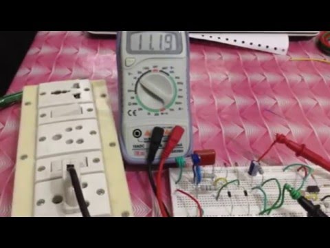
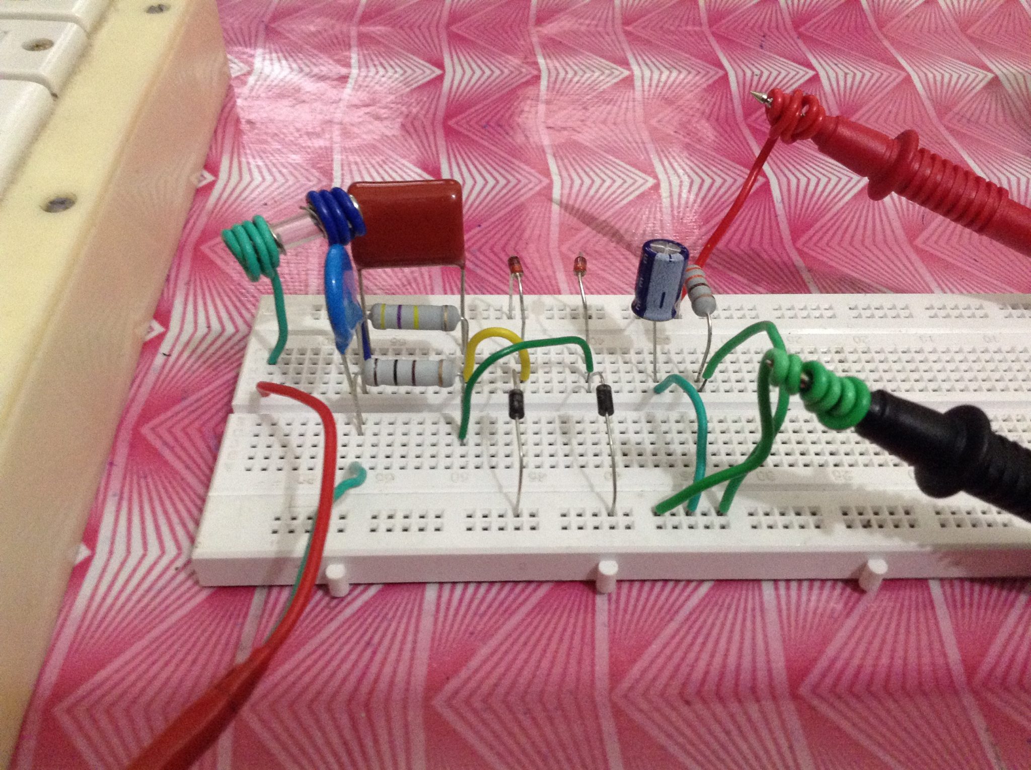
Experiments
In our experiment we used resistors with higher rating than we got in calculation. You don’t need to use this much big resistors. Here we used a load resistor of 300Ω to test the current driving capability.
Output Voltage = Vz – Vd = 12 – 0.7 = 11.3V

Warning
Don’t try this circuit if you don’t have much experience with electronics. Care should be taken while testing or using this circuit. Don’t touch at any points of the circuit since some points of this circuit is at Mains Potential. After constructing and testing, enclose the circuit in a metal casing without touching PCB and metal case. The metal case should be properly earthed to avoid shock hazards.
Video