Contents
In this project we will learn how to decode IR remote signals with Arduino and to control DC motors depending on the button pressed. For demonstrating the working we are using five buttons on the remote. When the next button on the remote is pressed, motors will rotate in clockwise direction. And if the previous button is pressed motors will rotate in anticlockwise direction. We can also control these two motors individually using left, right arrow buttons and stop button can be used to stop the rotation.
We are using 1838 IR receiver (AX-1838HS, TL1838, TSOP1838) for sensing IR signals transmitted from the remote. Arduino Uno is the brain of this project. We are using L293D motor driver IC to drive motor since Arduino won’t be able to supply enough current to drive a DC motor. L293D can drive two dc motors at the same time.
Components Required
- Arduino Uno
- IR Sensor 1838
- IR Remote (TV remote or any other IR remote will work fine)
- L293D DC Motor Driver IC
- 2x DC Motors
- 9V Battery
- Breadboard
- Connecting Wires
Circuit Diagram
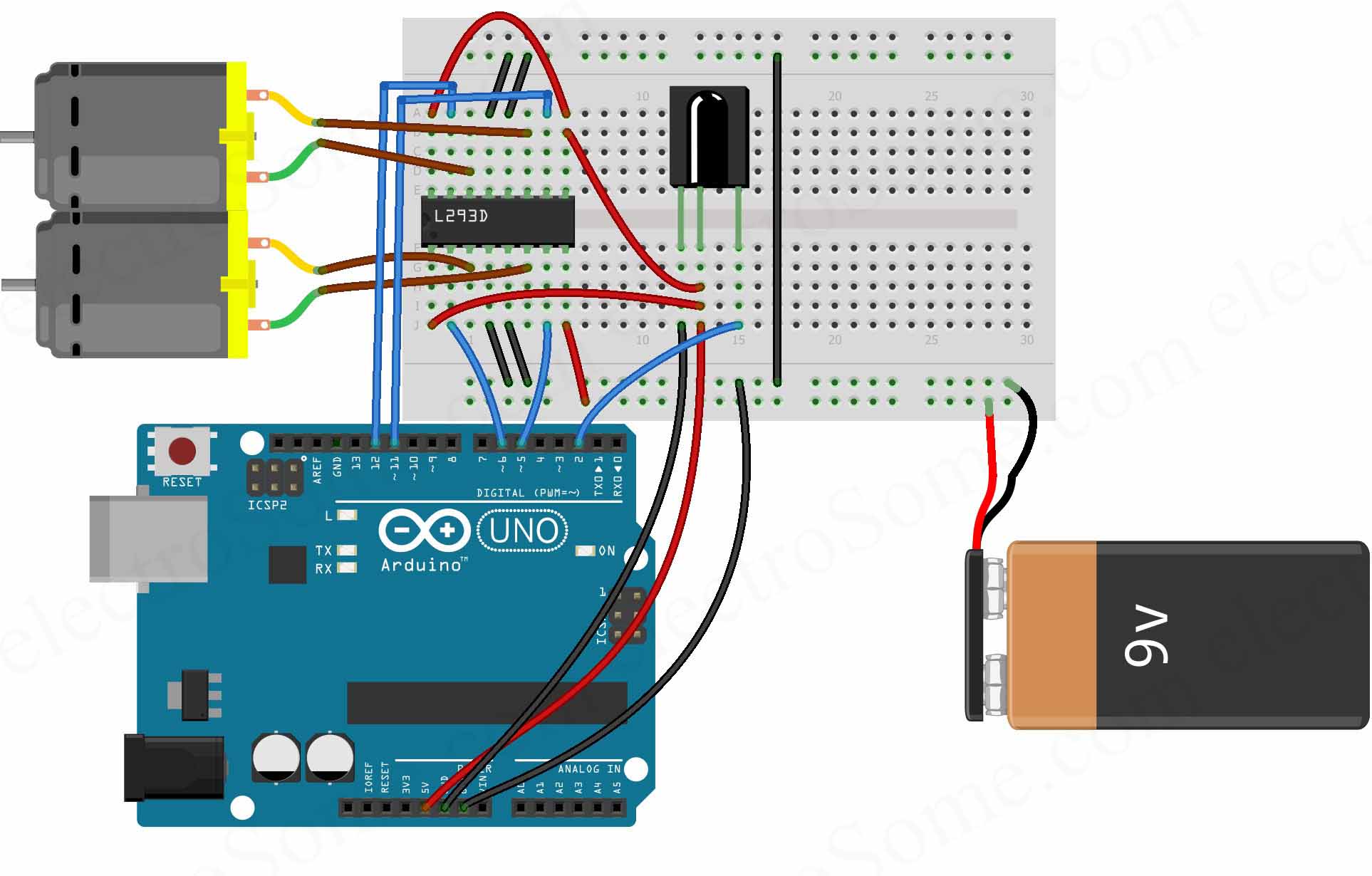
Firstly we can connect IR sensor to Arduino Uno.
- Connect the left pin of IR sensor which is ground to the ground of the Arduino
- Connect the middle pin which is 5V input to the 5V output pin of the Arduino.
- Connect the right pin which is signal output pin to the digital pin 2 of the Arduino.
We are using a 9V battery to power 2 DC motors.
Now we can connect L293D IC to Arduino Uno. The pin out of the IC is shown below.
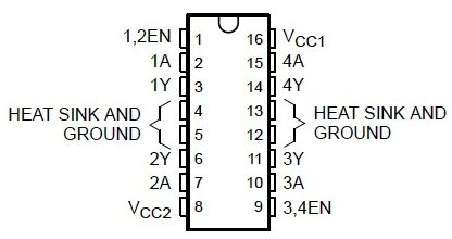
Connections are as follows :
- Connect enable pins (Pin 1, Pin 2) of L293D to 5V output of Arduino. This enables two H-Bridge channels inside the IC to drive two DC motors.
- Connect logic voltage input (Pin 16) of L923D to 5V output of Arduino. This defines the voltage (5V) logic of control signals .
- Connect motor/drive supply (Pin 8) of L293D to +ive of the 9V battery.
- Connect ground pins (Pin 4, 5, 12, 13) to ground of Arduino and -ive of the battery.
- Connect pin 2 of L293D to digital pin 6 of the Arduino.
- Connect pin 7 of L293D to digital pin 5 of the Arduino.
- Connect pin 10 of L293D to digital pin 11 of Arduino.
- Connect pin 15 of L293D to digital pin 12 of Arduino
- Connect first DC motor to Pin 3 and Pin 6 of L293D.
- Connect second DC motor to Pin 11 and Pin 14 of L293D.
Arduino IR Remote Library
You need to manually add IR Library to Arduino IDE as it is not included by default. You can ignore it if you already added it. Otherwise you can do following steps for that.
- Download Library : Arduino IR Remote Library.
- Open Arduino IDE.
- Go to Sketch >> Include Library >> Add .ZIP Library
- Select the downloaded ZIP file and press open.
Finding IR Remote Codes
Hope you already included IR remote library. Next step is to find CODES of required buttons in you IR Remote. Then we will use these decoded IR remote CODES in the main program to detect which button is pressed. You can use the following program to decode IR codes.
Program Code
#include <IRremote.h> //including the remote library
int receiver_pin = 2; //output pin of IR receiver to pin 2 of arduino
IRrecv receiver(receiver_pin); //Arduino will take output of IR receiver from pin 2
decode_results output;

void setup() {
  // put your setup code here, to run once:
  Serial.begin(9600);
  receiver.enableIRIn(); // Start to take the output from IR receiver
}

void loop() {
  if (receiver.decode(&output)) {
    unsigned int value = output.value;
    Serial.println(value);
    receiver.resume();
  }
}
IR Remote Codes in Serial Monitor
Run above code and open the serial monitor to view decoded codes. Press required buttons of your remote pointing towards the IR receiver. You can use any IR remotes like TV remote or even you can give signals from mobile by installing IR remote app (only if you mobile has IR transmitter). When you press buttons, you can see the decoded code of each buttons in the serial monitor as shown below.

Now you can copy these decoded IR remote codes to the main program (see below) for each function.
Program
#include <IRremote.h>      //including the remote library

#define Next_button 60891  // code received from next button
#define Prev_button 49467  // code received from previous button
#define left_button 58747  // code received from left button
#define right_button 15355 // code received from right button
#define Stop_button 7611   // code received from stop button

int receiver_pin = 2;      //output pin of IR receiver to pin 2 of arduino
//initializing the pins for leds
int left_motor1 = 11;      //pin 6 of arduino to pin 7 of l293d
int left_motor2 = 12;      //pin 7 of arduino to pin 2 of l293d
int right_motor1  =6;      //pin 5 of arduino to pin 10 of l293d
int right_motor2 = 5;      //pin 4 of arduino to pin 15 of l293d

IRrecv receiver(receiver_pin); //Arduino will take output of IR receiver from pin 2
decode_results output;

void setup() {
  Serial.begin(9600);
  receiver.enableIRIn(); // Start to take the output from IR receiver
  //initializing all the pins where we have connected the led's as output pins
  pinMode(left_motor1, OUTPUT);
  pinMode(left_motor2, OUTPUT);
  pinMode(right_motor1, OUTPUT);
  pinMode(right_motor2, OUTPUT);
}

void loop() {
  if (receiver.decode(&output)) {
    unsigned int value = output.value;
    switch(value) {
      case Next_button:
           digitalWrite(left_motor1,LOW);
           digitalWrite(left_motor2,HIGH);
           digitalWrite(right_motor1,HIGH);
           digitalWrite(right_motor2,LOW);
           break;
      case Prev_button:
           digitalWrite(left_motor1,HIGH);
           digitalWrite(left_motor2,LOW);
           digitalWrite(right_motor1,LOW);
           digitalWrite(right_motor2,HIGH);
           break;
      case left_button:
           digitalWrite(left_motor1,LOW);
           digitalWrite(left_motor2,HIGH);
           digitalWrite(right_motor1,HIGH);
           digitalWrite(right_motor2,HIGH);
           break;
      case right_button:
           digitalWrite(left_motor1,HIGH);
           digitalWrite(left_motor2,HIGH);
           digitalWrite(right_motor1,HIGH);
           digitalWrite(right_motor2,LOW);
           break;
      case Stop_button:
           digitalWrite(left_motor1,LOW);
           digitalWrite(left_motor2,LOW);
           digitalWrite(right_motor1,LOW);
           digitalWrite(right_motor2,LOW);
           break;
    }
    receiver.resume();
  }
}
Explanation
In the first section we are adding the IR library for decoding IR signals from the remote. Then we defined decoded codes of remote buttons that we got from the first program. I have added five buttons which will control both motors in clockwise, anticlockwise directions, individual left right motor control and a stop button.
#include <IRremote.h>      //including the remote library
#define Next_button 60891  // code received from next button
#define Prev_button 49467  // code received from previous button
#define left_button 58747  // code received from left button
#define right_button 15355 // code received from right button
#define Stop_button 7611   // code received from stop button
In the next section we are defining all digital input output pins of Arduino which are used in this project.
int receiver_pin = 2; //output pin of IR receiver to pin 2 of arduino
//initializing the pins for leds
int left_motor1 = 11; //pin 6 of arduino to pin 7 of l293d
int left_motor2 = 12; //pin 7 of arduino to pin 2 of l293d
int right_motor1 = 6; //pin 5 of arduino to pin 10 of l293d
int right_motor2 = 5; //pin 4 of arduino to pin 15 of l293d
After that we are we are initializing the IR library and digital pins.
IRrecv receiver(receiver_pin); //Arduino will take output of IR receiver from pin 2
decode_results output;

void setup() {
  Serial.begin(9600);
  receiver.enableIRIn(); // Start to take the output from IR receiver
  //initializing all the pins where we have connected the led's as output pins pinMode(left_motor1, OUTPUT);
  pinMode(left_motor2, OUTPUT);
  pinMode(right_motor1, OUTPUT);
  pinMode(right_motor2, OUTPUT);
}
Now in the main program the following section will decode the received IR signal and will be stored in the variable named ‘value’. After that we have made different conditions using switch statement. If the code received will match any of these conditions then motors will be switched accordingly.
if (receiver.decode(&output)) {
  unsigned int value = output.value;
  switch(value) {
    case Next_button:
         digitalWrite(left_motor1,LOW);
         digitalWrite(left_motor2,HIGH);
         digitalWrite(right_motor1,HIGH);
         digitalWrite(right_motor2,LOW);
         break;
Working
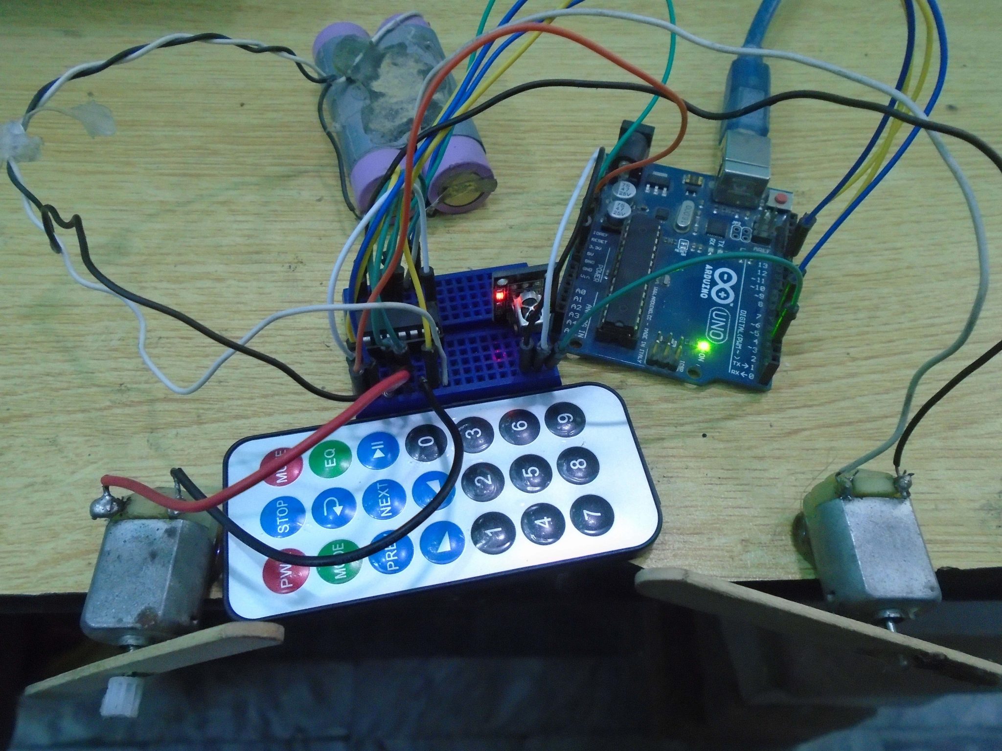
You can watch the following video to see how it works.
Video
