
Contents
In this tutorial we will learn how to program PIC 18F Microcontrollers using MikroC Pro compiler. I hope that you already know the basics of PIC Programming using MikroC compiler. If you are a beginner to this field, please read our first tutorial Blinking LED using PIC Microcontroller – MikroC. There are a lot of advantages for PIC 18F microcontrollers compared to 16F. Some of them are given below.
- PIC 18F is optimized for C while PIC 16F is not.
- PIC 18F has interrupt priority (high and low priority) while PIC 16F doesn’t.
- PIC 18F has internal PLL (Phase Locked Loop) to multiply clock frequency and by thus increases the operating speed.
- PIC 18F has more memory.
- PIC 18F has hardware multiplier while PIC 16F doesn’t.
- PIC 18F has more instructions than PIC 16F which makes assembly language programming simpler and it also reduces the size of HEX File generated in other compilers.
- PIC 18F eliminates Read Modify Write Problems with Mid-Rang PIC Microcontrollers.
- In PIC 18F, we needn’t bother about bank switching but in PIC 16F it is a big problem if we are using assembly language programming.
In 16F PIC Microcontrollers we have two registers to control IO pins, which are TRIS and PORT. TRIS is used to control direction (Input or Output) of each IO pin while PORT is used to Write or Read data from IO pins. Whereas in 18F PIC Microcontrollers there is an additional register, LAT. LAT stands for Port Latch. As in 16F, 18F also uses TRIS register to control direction of each IO pin. LAT register is used to write Output and PORT register is used read Inputs. I recommend you to read the article Read Modify Write Problems with PIC Microcontrollers for understanding the internal working of LAT register.

Working of TRIS, PORT and LAT registers can be understand from the above diagram. Logic High (1) at TRIS register makes corresponding pin of PIC microcontroller Input while Logic Low (0) at TRIS register makes corresponding pin Output. When a pin is configured as Input, it will be in High Impedance state and its physical state (voltage level) can be read using PORT register. When a pin is configured as Output, its output logic state will be determined by LAT register. 1 at LAT register makes corresponding pin Logic High (VDD) and 0 a t LAT register makes corresponding pin Logic Low (VSS). LAT register bits corresponding to Input pins have no effect on Output or Input, thus they are Don’t Care. Following points should be noted.
- LAT write operation writes LAT register.
- LAT read operation reads LAT register.
- PORT write operation writes LAT register.
- PORT read operation reads the physical state (voltage level) of all the pins.
Thus you can write outputs using PORT write or LAT write operation but using PORT write operation is not recommended as it may cause RMW Problem.
MikroC Programming
You can write PORT and TRIS registers entirely or bit by bit.
Writing Bit by Bit :
TRISC.F0 = 1; //Makes 0th bit of PORTC Input
TRISC.F5 = 0; //Makes 5th bit of PORTC Output
LATC.F3 = 1; //Makes 3rd bit of PORTB at Logic High
LATC.F7 = 0; //Makes 7th bit of PORTB at Logic Low
Writing Entire Register
- A number with a prefix ’0b’ indicates a binary number.
- A number with a prefix ’0′ indicates an octal number.
- A number with a prefix ’0x’ indicates a hexadecimal number.
- A number without prefix is a decimal number.
Let’s see some examples…
| Decimal | Binary | Octal | Hexadecimal |
|---|---|---|---|
| 0 | 0b00000000 | 00 | 0x00 |
| 1 | 0b00000001 | 01 | 0x01 |
| 128 | 0b10000000 | 0200 | 0x80 |
| 255 | 0b11111111 | 0377 | 0xFF |
TRISB = 0; //Makes all pins of PORTB Output
LATB = 0xFF; //Makes all pins of PORTB Logic High
TRISC = 255; //Makes all pins of TRISC Input
TRISD = 0200; //Makes 7th pin of PORTD Output
LATD = 0b10000000; //Makes 7th pin of PORTD Logic High
In this tutorial we will learn How to Read an Input pin and How to Write Output. For demonstration purpose we will use PIC 18F4550, a very common PIC Microcontroller. If you want to use any other 18F microcontroller, just select it while creating the project or edit it through MikroC Project Settings (Project >> Edit Project). I will recommend 18F452 and 18F4520 as they are also very common and their pins are compatible with PIC 16F877A. Here an LED is connected to 15th pin (RC0) of 18F4550 via a current limiting resistor. Hence the 15th pin should be configured as an Output Pin. Similarly Push Button Switch is connected to 19th (RD0) pin which should be configured as Input Pin.
If you haven’t yet started with MikroC, please read the tutorial Blinking LED using PIC Microcontroller.
MikroC Code – Control LED using Switch
void main()
{
  TRISC.F0 = 0; //PORTC0 Output
  TRISD.F0 = 1; //PORTD0 Input
  LATC.F0 = 0; //LED OFF
  while(1)
  {
    if(PORTD.F0 == 0)//IF Switch Pressed
    {
      LATC.F0 = 1; //LED On
      Delay_ms(2000); //2 Second Delay
      LATC.F0 = 0; //LED Off
    }
  }
}
Delay_ms() is a predefined function in MikroC Pro which will provide delay in milliseconds.
Circuit Diagram
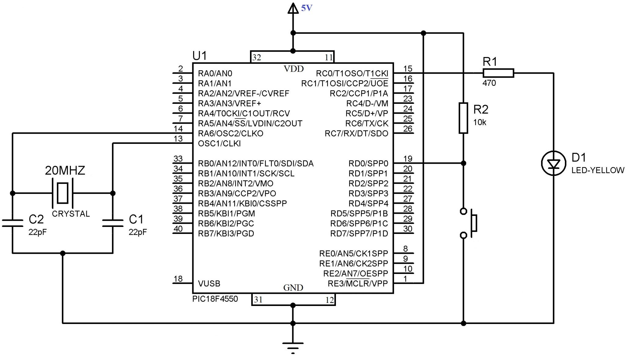
VDD and VSS of PIC Microcontroller is connected to +5V and GND respectively to provide necessary power for the operation of the microcontroller. 20MHz crystal is used to provide necessary clock for the microcontroller. 22pF capacitors stabilizes the oscillations of the crystal. LED is connected to the 0th bit of PORTC (15th pin) and a 470Ω resistor is connected in series to limit the current through the LED. Switch is connected to 0th bit of PORTD (19th pin) and a 10KΩ resistor is used as PULL UP. It ensures that 19th pin will be in HIGH state when the switch is not pressed.
You can download MikroC and Proteus files here.