
Contents
I hope that you have already read the first tutorial of Hi Tech C, LED Blinking using PIC Microcontroller. In that tutorial we blink LEDs connected to PORTB by writing to entire PORT and TRIS registers. In some cases we may want to set or reset individual bits of these registers. For that we can use the bit addressable feature of these registers. We have already seen in the previous tutorial that TRIS register is used to set the direction of each bits and PORT register is used to set the status of each bits in a port. A HIGH (1) at a bit of TRIS register makes the corresponding pin input and LOW (0) makes it output. In Hi-Tech C we can use following methods to write to TRIS and PORT registers.
Prerequisites
Writing a Register
TRISB = 0x0F // In binary TRISB = 0b00001111

PORTB = 0xF0 // In binary PORTB = 0b11110000
Writing Bit
TRISB0 = 1 // Makes RB0 a input pin

RB0 = 1 // Makes RB0 HIGH (VDD)
In this tutorial we will define a pin as input and another pin as output. A push button switch is connected to the input pin and the output pin drives an LED. When the switch is pressed, the LED glows for 2 seconds.
Circuit Diagram
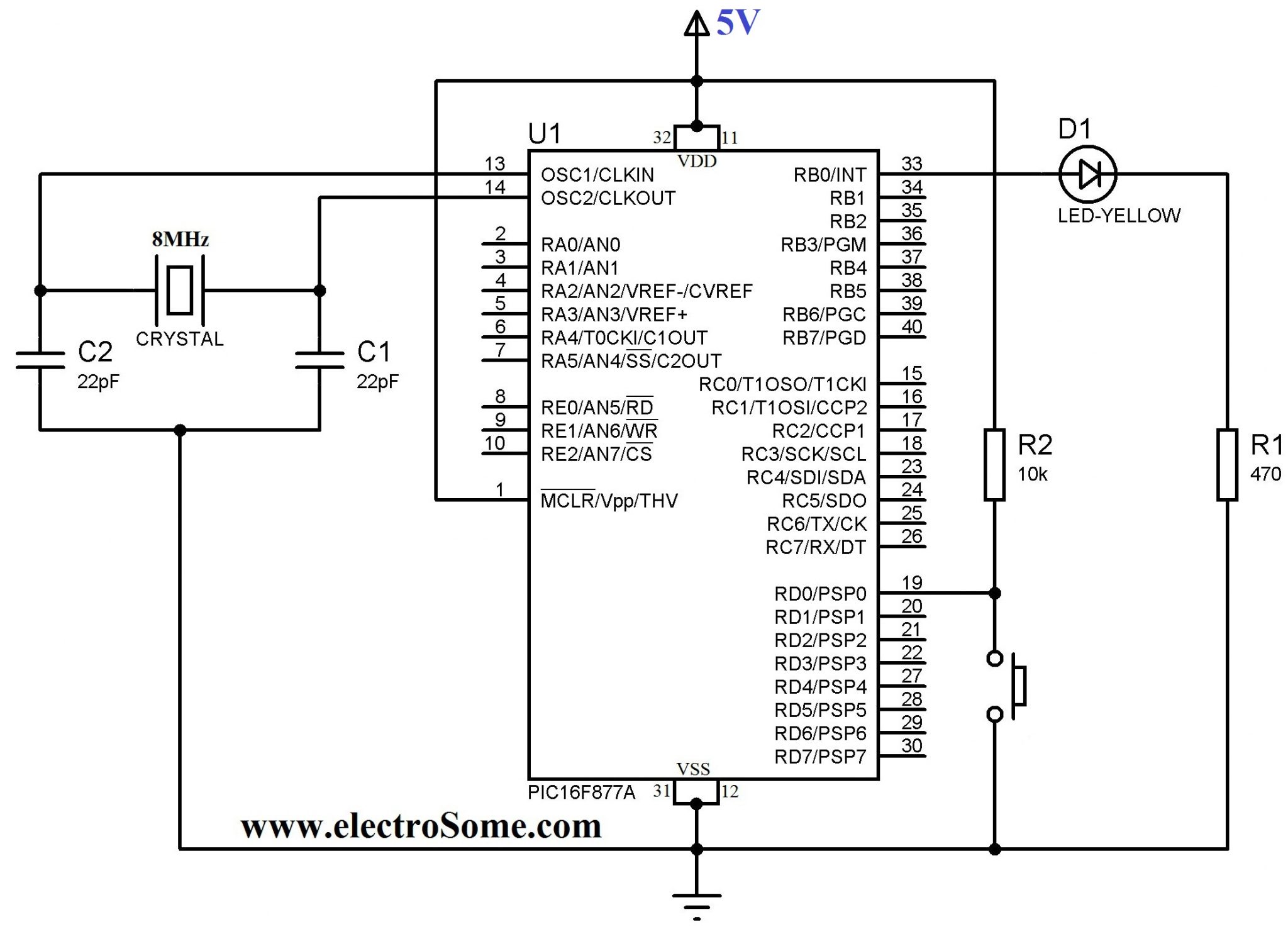
Pin RD0 is defined as an input pin, which is used to connect push button switch and pin RB0 is defined as an output pin, which drives an LED. RD0 is pull up to VDD using a 10KΩ resistor such that when the switch is not pressed the pin will be at the potential VDD and when the switch is pressed it will be grounded. A 470Ω resistor is connected in series with LED to limit the current through it.
Hi-Tech C Code
#include <htc.h>
#define _XTAL_FREQ 8000000
void main()
{
  TRISD0 = 1; //RD0 as Input PIN
  TRISB0 = 0; //RB0 as Output PIN
  RB0 = 0; //LED OFF
  do
  {
    if(RD0 == 0) //If Switch is presseed
    {
      __delay_ms(100); //Provides required delay
      if(RD0 == 0) //If Switch is still pressed
      {
        RB0 = 1; //LED ON
        __delay_ms(2000); //2 second delay
        RB0 = 0; //LED OFF
      }
    }
  }while(1);
}
I hope that most parts of the above program are explained in its comments. 100ms delay between reading status of switch is provided for following reasons.
- The above program executes in 8MHz but the time period required for closing and opening the connection of switch varies from 100 – 300ms. Thus a delay must be provided while reading status of a switch. For eg: If you haven’t used delay while reading switch status which is used to counting, it will count multiple times with a single press.
- It will avoid false triggering by makes sure that the switch is being pressed after a delay.
- It will provide Switch Debouncing
Download Here
You can download Hi-Tech C files and Proteus files here…