Contents
I hope that you already go through the first tutorial of MPLAB XC8, Getting Started with MPLAB XC8 – LED Blinking. In that tutorial we learn how to use an output pin by driving an LED. In this we will learn how to read an Input pin using a push button switch. We already seen that TRIS register is used to set direction of each IO pin, ie Input or Output and PORT register is used to read or write status of an IO pin. 1 at TRIS bit makes the corresponding pin Input while 0 at TRIS bit makes the corresponding pin Output. An Input pin will be in Hi-Impedance state.Writing 1 to PORT bit corresponding to an Output pin makes the pin Logic High (VDD) while writing 0 to PORT bit makes the corresponding Output pin Logic Low (VDD). PORT register can be used to read physical state (actual voltage level) of an input pin. If an Input pin is at a potential near to VDD, reading PORT bit will give 1 and if the input pin is at a potential near to VSS, reading PORT bit will give 0.
In this tutorial a push button switch is connected to a pin declared as input (TRIS bit 1) and an LED is connected to a pin declared as output (TRIS bit 0). When the switch is pressed, the LED will glow for 3 seconds.
Circuit Diagram
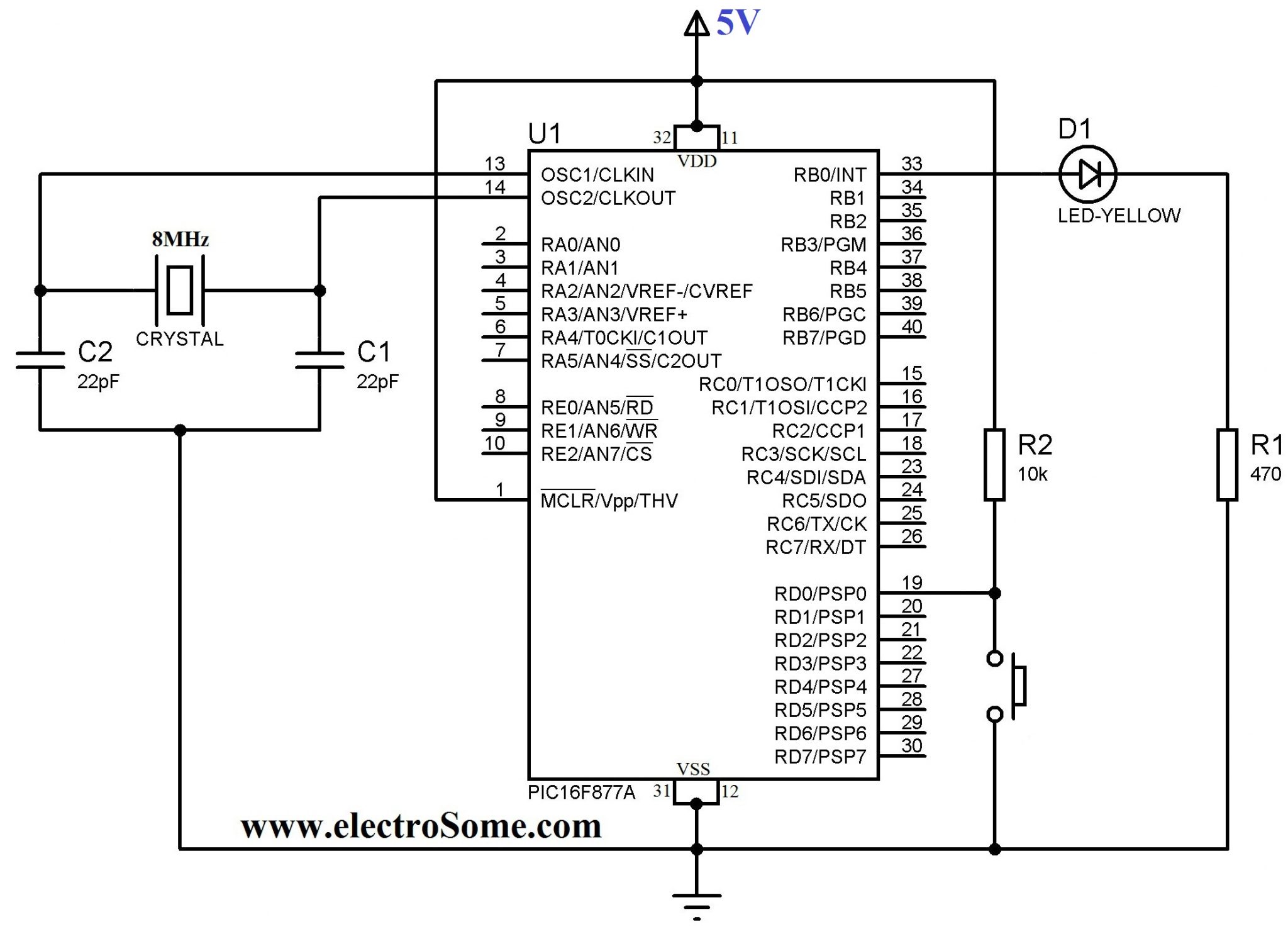
VDD and VSS of PIC Microcontroller is connected to +5V and GND respectively to provide the necessary power for the operation of microcontroller. 8MHz crystal is used to provide necessary clock for the operation of microcontroller. Pin RD0 (PIN 19) is declared as an input pin (TRIS bit 1) to which push button switch is connected. Pin RB0 (PIN 33) is declared as an output pin (TRIS bit 0) to which LED is connected. A 10KΩ PULL UP resistor is used along with push button switch to ensure that RD0 is at Logic High (VDD) when the switch is not pressed. Whenever the switch is pressed, RD0 becomes Logic Low (VSS). A 470Ω resistor is used to limit the current through the LED.
MPLAB XC8 Code
#define _XTAL_FREQ 8000000

#include <xc.h>

// BEGIN CONFIG
#pragma config FOSC = HS // Oscillator Selection bits (HS oscillator)
#pragma config WDTE = ON // Watchdog Timer Enable bit (WDT enabled)
#pragma config PWRTE = OFF // Power-up Timer Enable bit (PWRT disabled)
#pragma config BOREN = ON // Brown-out Reset Enable bit (BOR enabled)
#pragma config LVP = OFF // Low-Voltage (Single-Supply) In-Circuit Serial Programming Enable bit (RB3 is digital I/O, HV on MCLR must be used for programming)
#pragma config CPD = OFF // Data EEPROM Memory Code Protection bit (Data EEPROM code protection off)
#pragma config WRT = OFF // Flash Program Memory Write Enable bits (Write protection off; all program memory may be written to by EECON control)
#pragma config CP = OFF // Flash Program Memory Code Protection bit (Code protection off)
//END CONFIG

int main()
{
  TRISB0 = 0; //RB0 as Output PIN
  TRISD0 = 1; //RD0 as Input PIN

  RB0 = 0; //LED Off

  while(1)
  {
    if(RD0 == 0) //If Switch Pressed
    {
      RB0 = 1; //LED ON
      __delay_ms(3000); //3 Second Delay
      RB0 = 0; //LED OFF
    }
  }
  return 0;
}
I hope that you can understand program through its comments. In some cases you may need to recheck the switch is being pressed after a delay, like the following.
if(RD0 == 0) //If Switch is presseed
{
  __delay_ms(100); //Provides required delay
  if(RD0 == 0) //If Switch is still pressed
  {
    RB0 = 1; //LED ON
    __delay_ms(3000); //3 second delay
    RB0 = 0; //LED OFF
  }
}
You should recheck the status of the switch after a small delay due to following reasons.
- As the clock frequency is 8MHz, the program is running with that speed but the closing and opening of switch varies from 100 – 300ms. Thus a delay should be provided while reading switch. For eg : If you haven’t used delay while reading status of a switch which is used for counting purposes, it may count multiple times with a single press due to high speed of program execution.
- It will avoid false triggering by makes sure that switch is being pressed after a delay.
- It will provide Switch Debouncing.
Download Here
You can download the entire project files here . . .