
Contents
What is an EEPROM ?
EEPROM is an abbreviation for Electrically Erasable Programmable Read Only Memory and it is a Non-Volatile memory. It is used in computers and other electronic devices to store data that must me saved during no power supply. EEPROM is a class of ROM (Read Only Memory) which can be electrically erased in bit by bit and able to store new data. A small amount of EEPROM (usually 128/256 bytes) is available internally with PIC Microcontrollers. I have already posted about Using Internal EEPROM of PIC Microcontroller. But if the amount of data that we required to store in EEPROM is large, say in the order of Kilobytes then we have to interface external EEPROM with PIC Microcontroller.
There are many types of EEPROM chips are available from a number of manufactures. 24C series are the one of the most popular serial EEPROMs. It uses I2C (Inter-Integrated Circuit) bus to interface with Microcontroller and are available up to 128KB. I2C is a multi-master serial single ended computer bus used to interface low speed devices to a cellphone, embedded system, mother board or other electronic devices.
Here we are using 24C64 64K serial EEPROM. 24C64 works as a slave device on I2C bus. Register access can be obtained by implementing a START signal followed by device identification address. Then each memory locations can be accessed by using its address until a STOP condition is executed.
Pin Descriptions of 24C64 EEPROM
- A0, A1, A2 – Chip Address Inputs : These inputs are used for multiple device operations. The logic levels on

24C64 Pin Diagram these input pins are compared with the corresponding bits in the slave address and the chip is selected if the compare is true. Thus up to eight devices can be connected to same bus using different chip select bit combinations.
- WP – Write Protect : When this pin is kept LOW (grounded) normal read and write operations are possible but when it is HIGH (Vcc) write operations will be inhibited. The internal PULL DOWN resistor of this pin keep the device unprotected when it is left floating.
- Vcc and Vss : Vcc is the positive DC supply pin. The device is able to work with in 1.8 to 5.5V range. Vss is the ground pin (0v).
- SDA – Serial Data : This is bidirectional pin used to transfer data and address to and from the device.
- SCL – Serial Clock : This pin is used to synchronize data transfer through SDA.
Device Addressing

Control Byte is the first byte received by a slave device after receiving start signal from a master device. For 24C64 first 4 bits are control code (1010) for the device identification. Next 3 bits of the control byte are Chip Select Bits (A2, A1, A0). These bits allows us to connect up to eight 24XX64 devices on the same bus. The Chip Select Bits of control byte must be correspond to the logic levels of A2, A1, A0 of the device to be selected. The last bit of Control Byte is used to define the operation to be performed. It is set to 1 when read operation is to be performed and set to 0 when write operation is to be performed.
Read the Next Page to read about reading and writing data from/to EEPROM. Please Jump to this page if you don’t need detailed explanation.
Writing Data to EEPROM
We can write data to 24C64 in two ways.
Byte Write
In this mode one byte is written at a time. After giving the START signal, the master send control byte, the control code (four bits), the chip select (three bits), and the R/W bit (which is a logic low) via I2C bus. This indicates the addressed device that, higher order address of memory location to be written will be follow after it has generated acknowledge signal. Thus next byte transmitted by master device will be higher order address and it will be stored in the address pointer of the 24XX64. The Least Significant Address byte will be followed after it has generated acknowledge signal. Then the master device will send data to written the address location. When the 24XX64 acknowledges, the master issues stop signal.

Note: Some delay should be given between sequential write processes otherwise write cycle may not occur.
Page Write
Page write is similar Byte write, instead of generating STOP signal master transmits up to 31 additional bytes. These are temporarily stored in the on-chip page buffer and will be written in to memory after the master has given STOP signal. If the master sends more than 32 bytes, previously written data will be over written.

Note: Some delay should be given between sequential write processes otherwise write cycle may not occur.
Reading Data From EEPROM
Data can be read from 24XX64 EEPROM in 3 ways.
Current Address Read
The 24XX64 EEPROM contains an internal counter which maintains address of last memory location accessed, incremented by one internally. Thus upon receiving control byte with read/write control bit set to 1, 24XX64 issues acknowledge signal and transmits the 8-bit data word in the next memory location.

Random Read
Random read operation allows master to access any memory location in random manner. To perform this type of operation, we want to set the address in internal address counter to the required value. This is achieved by sending address to 24XX64 EEPROM as the part of write operation. After the acknowledge of this process, the master issues a START signal and control byte for read operation. Thus the required random memory location can be easily accessed.

Sequential Read
Sequential Reading is initiated in a similar way as Random Read, except that after the 24XX64 EEPROM transmits first data byte master issues acknowledge signal instead of STOP signal in Random Read operation. This will direct 24XX64 EEPROM to send next data byte.

Please Read Next Page to read about MikroC Programming.
MikroC Programming
MikroC Pro for PIC Microcontroller provides built-in library routines to communicate with I2C devices. Here we deals only with Byte Write and Random Read operations. Using these you can easily make programs for other operations.
MikroC Function for Write Data to EEPROM :
void write_EEPROM(unsigned int address, unsigned int dat)
{
  unsigned int temp;
  I2C1_Start(); // issue I2C start signal
  I2C1_Wr(0xA0); // send byte via I2C (device address + W)
  temp = address >> 8; //saving higher order address to temp
  I2C1_Wr(temp); //sending higher order address
  I2C1_Wr(address); //sending lower order address
  I2C1_Wr(dat); // send data (data to be written)
  I2C1_Stop(); // issue I2C stop signal
  Delay_ms(20);
}
MikroC Function to Read Data from EEPROM :
unsigned int read_EEPROM(unsigned int address)
{
  unsigned int temp;
  I2C1_Start(); // issue I2C start signal
  I2C1_Wr(0xA0); // send byte via I2C (device address + W)
  temp = address >> 8; //saving higher order address to temp
  I2C1_Wr(temp); //sending higher order address
  I2C1_Wr(address); //sending lower order address
  I2C1_Repeated_Start(); // issue I2C signal repeated start
  I2C1_Wr(0xA1); // send byte (device address + R)
  temp = I2C1_Rd(0u); // Read the data (NO acknowledge)
  I2C1_Stop();
  return temp;
}
Circuit Diagram for Demonstration :
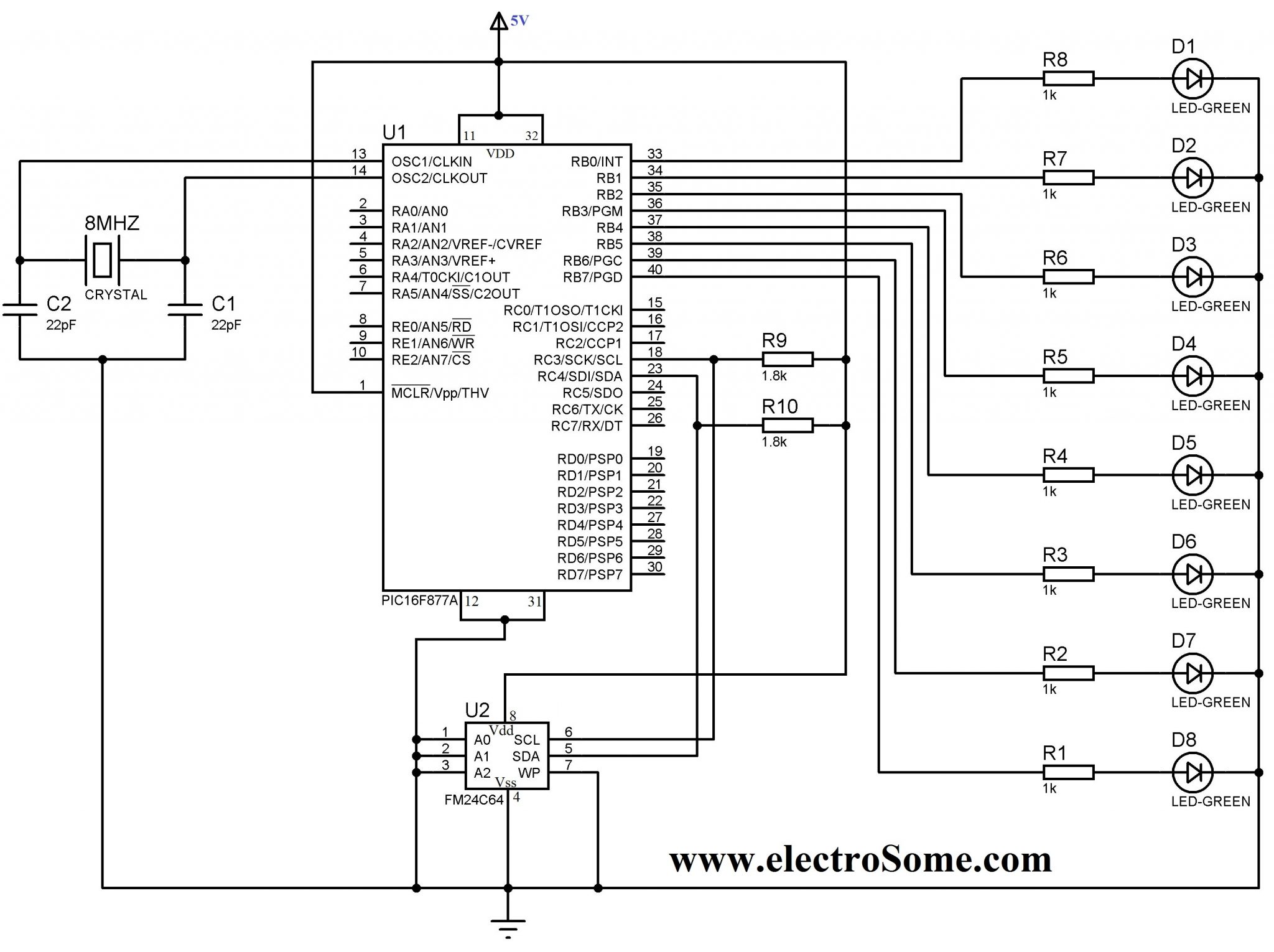
In this example we writes 00000001 to the first memory location, 00000010 to second, 000000100 to third etc sequentially up to 10000000. Then it is read sequentially and output through PORTB.
To simulate this project in Proteus you may need to connect I2C Debugger. SCL and SDA of I2C Debugger should be connected in parallel to SCL and SDA of 24C64. I2C Debugger can be found where CRO can be found in Proteus.
You can download the hex file, MikroC source code, Proteus files etc here…