Contents
One on the major part of our electronics products is the DC Power Supply that converts mains AC voltage to a lower DC voltage. Usually we use a step down transformer to reduce mains AC voltage to desired low voltage AC and then convert it to DC or we use Switched Mode Power Supplies. But in both cases cost is very high and it takes considerable amount of space. Another Low Cost alternative for Transformer and Switcher based power supply is Transformer Less Power Supply. There are basically two types of Transformer Less Power Supplies.
- Capacitive
- Resistive
The main difference between them is, in resistive transformer less power supply excess energy is dropped as heat across a voltage dropping resistor while in capacitor power supplies voltage is dropped across a voltage dropping capacitor so there is no energy loss or heat dissipation.
Capacitive TransformerLess or Capacitor Power Supply

In Capacitor Power Supplies we use a Voltage Dropping Capacitor in series with the phase line. An ordinary capacitor should not be used in these applications because Mains Spikes may create holes in dielectric of ordinary capacitors and the capacitor will fail to work. This may destroy the device by rushing current from the mains. Thus we use X Rated Capacitor with required voltage is used for this task. X Rated Capacitors rated for 250, 400, 600 V AC and higher are available. Reactance of the voltage dropping capacitor should be greater than the load resistance to keep constant current through the load.
Reactance of Capacitor, X = 1/2ΠfC
Where f is the frequency and C is the Capacitance. Thus a 0.22μF capacitor has reactance of 14.4KΩ on mains frequency (50Hz). The approximate value of maximum current can be find out by dividing mains voltage by reactance of the capacitor (since load resistance is small).
I = V/X
I = 230 V / 14. 4 = 15.9 mA
Thus a 0.22μF capacitor can supply a maximum current about 15mA.
Circuit Diagram
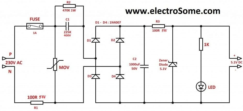
As shown 1A fuse may be used to avoid damages due to short circuit and a MOV (Metal Oxide Varistor) also may be connected as shown above to avoid problems due to voltage transients. The resistor R1 is used to limit the high current that may occur during power on. Capacitor C1 225K (2.2μF) is used as the Voltage Dropping Capacitor. A Bleeder resistor is connected parallel to it for discharging the capacitor when the supply is switched off. Diodes D1 – D4 is wired as Bridge Rectifier and the capacitor C2 is used to filter the pulsating DC. Zener Diode is used to regulate the filtered DC or you can use IC Voltage Regulator for better results. Resistor R3 is used to limit the current through the Zener Diode.
The following table shows the maximum current and open circuit voltage of some commonly used capacitors.
| Capacitor | Voltage | Current |
|---|---|---|
| 104K | 4 | 8 mA |
| 334K | 10 | 22 mA |
| 474K | 12 | 25 mA |
| 684K | 18V | 100 mA |
| 105K | 24V | 40 mA |
| 225K | 24V | 100mA |
Advantages
- Significantly smaller in size and lesser in weight than transformer power supplies.
- Lesser in Cost when compared to Transformer or Switcher based power supplies.
- Capacitor Power Supply is more efficient than Resistive Transformer Less Power Supply.
Disadvantages
- Higher Cost when compared to a Resistive Power Supply.
- No isolation from AC mains which introduces many safety issues.
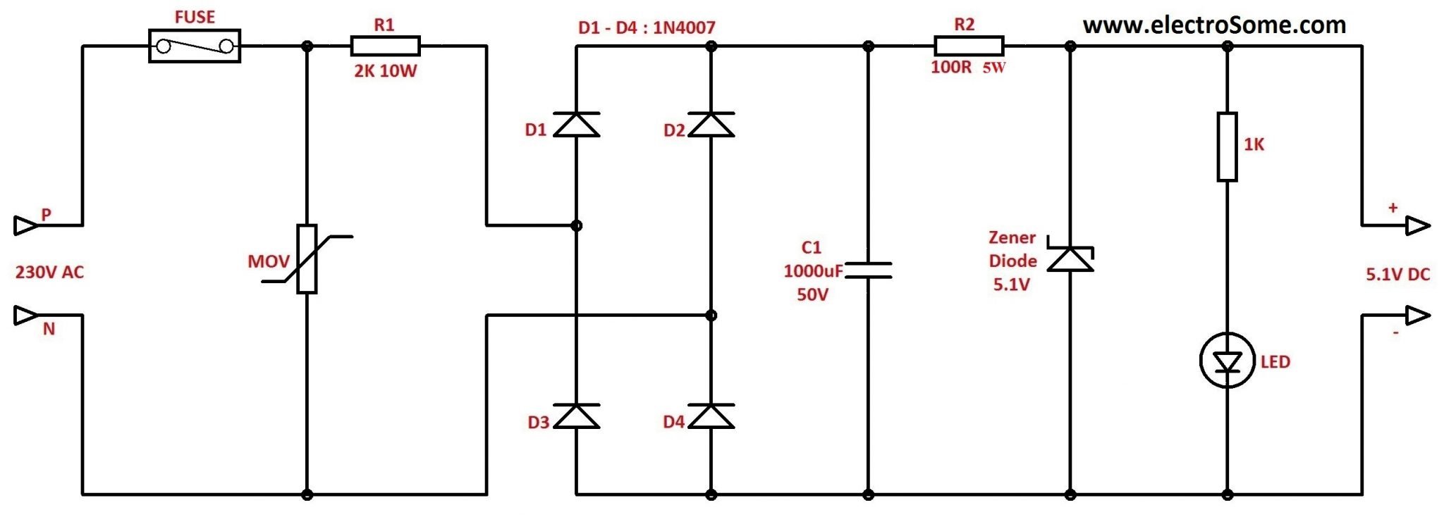
Resistive TransformerLess Power Supply
Resistive Transformer Less Power Supply is similar to Capacitor Power Supply except that instead of Reactance it uses resistance to limit current. Thus here excess energy is dissipated as heat across the Voltage Dropping Resistor.
Circuit Diagram
Care should be taken while selecting Voltage Dropping Resistor since the excess power is dissipated across it. Calculate power by multiplying Voltage and Current. P = VI
It is better to use a resistor of double the rated power.
Advantages
- Significantly small size and less weight than transformer based power supplies.
- Lesser Cost than Transformer or Switcher based power supplies.
- Lesser Cost than Capacitor Power Supply.
Disadvantages
- No isolation from AC Mains which introduces many safety issues.
- Resistive Power supplies are less efficient as the excess energy is losted in the form of heat across the Voltage Dropping Resistor.
Caution
Don’t Try this circuit if you don’t have much experience with electronics. Care should be taken while testing or using this circuit. Don’t touch at any points of the circuit since some points of this circuit is at Mains Potential. After constructing and testing enclose the circuit in a metal casing without touching PCB and metal-case. The metal case should be properly earthed to avoid shock hazards.