Interfacing LCD with PIC Microcontroller – MPLAB XC8

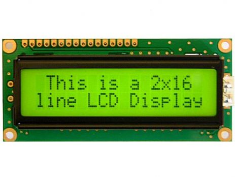
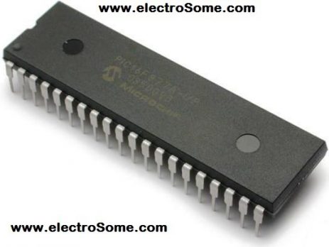
In this tutorial we will see How to Interface a 16x2 character LCD module with PIC 16F877A Microcontroller using MPLAB X IDE and MPLAB XC8 C Compiler. 16x2 Character LCD is a very basic and low cost LCD module which is commonly used in electronic products and projects. 16x2 means it contains 2 rows that can display 16 characters. Its other variants such as 16x1 and 16x4 are also available in the market. In these displays, each character is displayed...

Getting Started with MPLAB XC8 Compiler – LED Blinking

In this tutorial we will learn How to Blink an LED with PIC Microcontroller using MPAB XC8 Compiler. Recently Microchip released a series of development tools including MPLAB X IDE and MPAB XC Compilers. MPLAB X IDE is a software that runs on a computer intended to develop applications for Microchip's Microcontrollers and Digital Signal Controllers. It can be used with Windows, Mac and Linux Operating Systems. It is called an Integrated Development Environment as it provides comprehensive facilities to...

Configuration Bits in Mid-Range PIC Microcontrollers

Device Configuration Bits allows the programmer to adjust certain condition that determines the operation modes of the microcontroller. That is the state of Configuration Bits determines the mode in which device operates when it is powered. These configuration bits are mapped in the program memory location 2007h. This location can't be accessed during normal operation and can be accessed only at the time of programming. Their placement is automatically taken care by the device programmer or ICSP programmer. Hence selection...

Using ADC Module of PIC Microcontroller – Hi Tech C

Analog to Digital Converter (ADC) is a device that converts an analog quantity (continuous voltage) to discrete digital values. This is very useful when we want to do some processing on physical quantities, which are normally analog in nature. Most of the PIC Microcontrollers have built in ADC Module. Here we are using PIC 16F877A for demonstrating the working. ADC_Symbol ADC of PIC Microcontrollers have 5 inputs for 28 pin devices and 8 inputs for 40/44 pin devices. It is a 10-bit...

Pulse Width Modulation : PWM using Arduino

PWM using Arduino Pulse Width Modulation or PWM is a method of Digital to Analog Conversion. It helps in delivering analog average voltage using digital pulses of variable pulse width. By controlling the on time and off time, we can generate an analog average voltage using the digital pulses. PWM has a wide range of application. It is used in DC motor speed control, Brightness control of LED lamps etc. Here in this simple experiment to understand the PWM working in ARDUINO, we...

LED Blinking using 8051 Microcontroller and Keil C – AT89C51

8051 Microcontroller is a programmable device which is used for controlling purpose. Basically 8051 controller is Mask programmable means it will programmed at the time of manufacturing and will not programmed again, there is a derivative of 8051 microcontroller, 89c51 micro controller which is re-programmable. AT89C51 89c51 is 8-bit device means it is capable of doing 8-bit operations.  It have 4 ports which are used as input or output according to your need. This device also have Timer, Serial Port interface and Interrupt controlling you can use these according to your need. The datasheet may be downloaded from...

Interfacing Relay with PIC Microcontroller

A relay is an electromagnetic switch which is used to switch High Voltage/Current using Low power circuits. Relay isolates low power circuits from high power circuits. It is activated by energizing a coil wounded on a soft iron core. For detailed working of relay please visit this page. A relay should not be directly connected to a microcontroller, it needs a driving circuit. A relay should not be connected directly to a microcontroller due to following reasons.. A microcontroller is not able...

Analog to Digital Conversion in ARDUINO

Analog to digital conversion module of ARDUINO UNO has 6 input ports. The number of the port varies with your ARDUINO model but the coding remains the same. The analog reading in the analog inputs are converted into corresponding 10bit(0-1023). ARDUINO developers have made such an option that you can print anything and see it on the Serial monitor. This example demonstrates analog input usage by reading an analog sensor on analog pin 0 and turning on and off a light...

>