Interfacing DC Motor with PIC Microcontroller using L293D
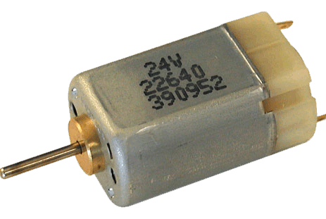
This tutorial explains " How to interface DC Motor with PIC Microcontroller ? ".
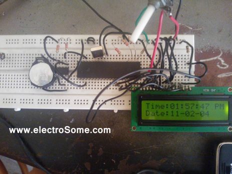
A Digital Clock can be made easily by using PIC Microcontroller, DS1307 and a 16x2 LCD. I have already posted about Interfacing DS1307 RTC with PIC Microcontroller. The DS1307 RTC can work either in 24-hour mode or 12-hour mode with AM/PM indicator. It automatically adjusts for months fewer than 31 days including leap year compensation up to year 2100. DS1307 comes with built-in power sensing circuit which senses power failures and...
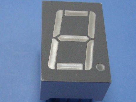
When a Seven Segment Display is interface with PIC Microcontroller it needs minimum 7 pins to display a value. But real time applications like Digital Clock, Calculator, Digital Watch requires 3-6 seven segment displays. Lets assume that we need 6 digit display, ie we need 7 segment * 6 Display = 42 pins. Thus we actually need Microcontroller with 42 output pins. This is waste and not economical to use lot of pins of a Microcontroller just for display. The simplest...
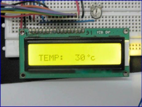
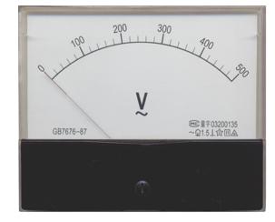
Voltmeter and Ammeter can be easily made using PIC Microcontroller having ADC (Analog to Digital Converter). I am using PIC16F877A and the result is displayed on an LCD Display. PIC16F877A is enough if you do this project only for testing purposes. I suggest to use PIC with low pin numbers and multiplexed 7 segment display if you wish to use this as your measuring instrument.
ADC module of PIC microcontroller have usually 5 input for 28 pin devices and 8 inputs for 40 pin devices. The conversion of analog signal to PIC ADC module results in corresponding 10 bit digital number. PIC ADC module has software selectable high and low voltage reference input to some combination of VDD, VSS, RA2 and RA3. In the following example project we will convert analog input to channel 1 to 10 bit digital number with low voltage reference (Vref-) 0v and...
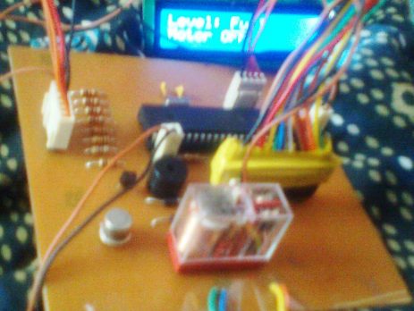
Here is a simple, versatile project which indicates the level of water and automatically controls it by using PIC Microcontroller. The Water Level Sensing Section senses the level of water in the tank and sends it (wireless) to the Receiver Section. Receiver Section is connected to the Controlling Section, which process the received information and produces visual, sound indications and controls the operation of the motor whenever required. The project is divide into 4 sections.
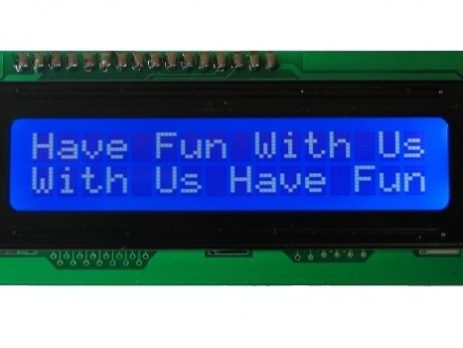
A PIC Microcontroller can be easily made to communicate with LCD by using the built in Libraries of MikroC. Interfacing between PIC and LCD can be 4-bit or 8-bit. The difference between 4-bit and 8-bit is how data are send to the LCD. In the 8-bit mode to write an 8-bit character to the LCD module, ASCII data is send through the data lines DB0- DB7 and data strobe is given through the E line. But 4-bit mode uses only 4 data lines. In this mode the...