Electronics tutorials including microcontroller, microprocessor, programing and circuits. Intended for beginners, electronics hobbyists, college students, professionals and educational purposes.

Getting Started with PIC 18F Microcontroller – MikroC

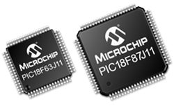
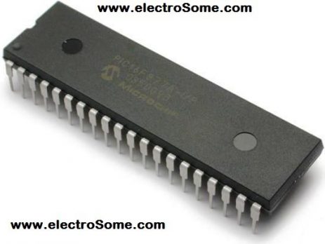
In this tutorial we will learn how to program PIC 18F Microcontrollers using MikroC Pro compiler. I hope that you already know the basics of PIC Programming using MikroC compiler. If you are a beginner to this field, please read our first tutorial Blinking LED using PIC Microcontroller - MikroC. There are a lot of advantages for PIC 18F microcontrollers compared to 16F. Some of them are given below. ...

Arduino – Development Board For Beginners

Arduino Uno R3 Arduino is a development board based on Atmel Microcontroller introduced in 2005. It is intended for beginners in the field of electronics. This can take inputs from different switches, sensors and can given output to surroundings through light, sound, motion etc. This is the most convenient method for computer based students to develop electronic projects with basic knowledge in electronics. It is an open source system which is flexible and is easy to use. Arduino has its...

Read Modify Write Problem with Mid-Range PIC Microcontrollers

RMW Problem with PIC 16F Family

Microchip's mid-range PIC Microcontrollers use a sequence of operations : Read, Modify and Write to change output state of a pin. In certain circumstances RMW operations might cause unexpected behavior of outputs. You might have already experienced this issue and struggled with it as you can't find exact reason with microcontrollers unexpected behavior. Mid-Range PIC Microcontroller uses two registers, TRIS and PORT to control the direction and status of an IO pin respectively. When you try...

Configuration Bits in Mid-Range PIC Microcontrollers

Device Configuration Bits allows the programmer to adjust certain condition that determines the operation modes of the microcontroller. That is the state of Configuration Bits determines the mode in which device operates when it is powered. These configuration bits are mapped in the program memory location 2007h. This location can't be accessed during normal operation and can be accessed only at the time of programming. Their placement is automatically taken care by the device programmer or ICSP programmer. Hence...

Getting Started with PL2303 USB to UART Converter

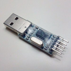
USB to UART Converter is a very useful tool for Embedded Systems. If you haven't one, please try to buy it. It will definitely boost development speed of projects which uses UART modules like interfacing GSM, GPS, Bluetooth, Wi-Fi ...  By using it we can easily study these modules by sending data directly from your PC and analyzing the received data in your computer display without programming a microcontroller. Here we will use PL2303, one of the most popular USB...

Flow Control in Python

What are Control Flow statements?

We often come across situations in which we need to divert or change the usual sequential flow of execution. The flow control statements can be classified into Conditional Statements and Iteration Statements. The Conditional Statements selects a particular set of statements for execution depending upon a specified condition. While the Iteration Statements repeatedly executes a block of statements with respect to some condition. This article assumes that you have basic knowledge in programming languages like C....

AM Generation using Simulink

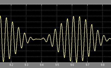
Amplitude modulation (AM) is a one of the conventional technique used to transmit message signals using a carrier wave. The amplitude or strength of the high frequency carrier wave is modified in accordance with amplitude of the message signal. If you are a newbie to Simulink, please read our article Introduction to Simulink. First of all lets get into the basics.. Carrier signal (Sc) = Acsin(2πfct) Message signal (Sm) = Amsin(2πfmt)   # fm must be smaller than fc When...

Generating PWM with PIC Microcontroller using Hi-Tech C

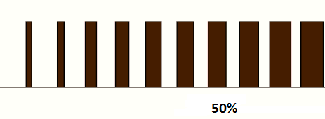
PWM (Pulse Width Modulation) is a powerful technique used to generate analog voltage using digital signals. It has a wide variety of applications such as controlling average power delivered to a load, generating analog voltage level, sine wave generation and DC Motor speed control. PWM signals are ON-OFF signals (hence the name Pulse) whose ON duration are changed (hence Width Modulation) according to our requirements. The fraction of time period for which the signal is ON to total time period is...

>