Hobby circuits for electronic hobbyists and students. With circuit diagram, pcb design and working explanation. 100% tested and working circuits.

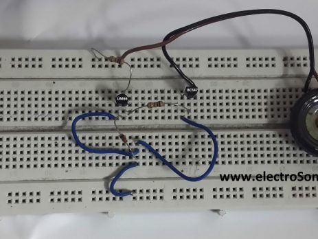
UM66 Melody Generator – First Step for Electronics Hobbyists

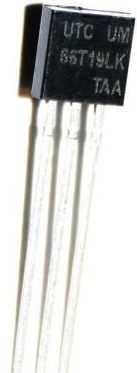
UM66 UM66 is a melody generating IC commonly used in calling bell, phone, toys, musical bell in doors, home security alarm systems, burglar alarms etc. It is a three pin IC looks like a transistor. Its first pin is ground, second is VCC and the third is the melody output. Supply voltage that can be given to the IC is in the range of 1.5V- 4.5V. These are CMOS ICs and have very small power consumption. Melody generator will reset when the...

IR Remote Control for Home Appliances

IR Remote Control for controlling home appliances can be easily made using Decade Counter CD4017, 555 Timer and TSOP1738 infrared receiver. By using this circuit you can easily control your home appliances using your TV, DVD Player remote control or using a remote control circuit described here. Remote Control Receiver Circuit Diagram IR Remote Control for Home Appliances 2nd and 1st pins of TSOP1738 are used to give power, Vcc and Gnd respectively. 100Ω resistor and 33μF capacitor is to suppress power supply...

Dancing Light using 555 Timer

A dancing light can be easily constructed using a 555 timer wired in astable mode. Please read the article Astable Multivibrator using 555 Timer before continuing. This circuit blinks two LEDs alternatively with some delay and it can be easily modified to include more LEDs or for controlling incandescent lamps. Time period of oscillation is determined by RC time constant of the circuit. Circuit Diagram Dancing Light using 555 Timer - Circuit Diagram 1st and 8th pins of 555 timer are used to provide power, Vcc and...

Low Power Square Wave Inverter using CD4047

Inverter is a electrical device that converts DC Power to AC. We usually use the word Inverter for the device used in our households for mains power back up. It stores electrical energy in a battery and discharges it when need. Our household inverters mainly have two parts, Battery Charging Circuit and Inverter Circuit. Battery charging circuit charges the battery when power is available, which may be mains power, solar power or any other sources and the Inverter Circuit convert...

Solar Tracker system Using LM358

We all know that a Solar Panel can be used to convert light energy to electrical energy. The amount of converted energy depends on the amount of light falling on the Panel. Generally Solar Panels are stationary devices which is fixed at a position. The produced electrical energy can be increased if we move the solar panel as the movement of the Sun. Here is a simple low cost Solar Tracker circuit which automatically moves the solar panel in the...

Line Follower Robot – without using Microcontroller

After a long time I am presenting my new project Line Follower Robot without using Microcontroller. It is a simple circuit with a LM358 op-amp and is able to operate from 9v to 12V. The LM358 contains two op amps which are wired as comparators. Thus when the voltage at the non-inverting terminal (+) is higher than inverting terminal (-) its output will be high and when the voltage at the inverting terminal (-) is higher than non-inverting terminal (+) the output will be low....

TransformerLess Low Cost DC Power Supply : Resistive & Capacitive

One on the major part of our electronics products is the DC Power Supply that converts mains AC voltage to a lower DC voltage. Usually we use a step down transformer to reduce mains AC voltage to desired low voltage AC and then convert it to DC or we use Switched Mode Power Supplies. But in both cases cost is very high and it takes considerable amount of space. Another Low Cost alternative for Transformer and Switcher based power supply...

Simple Water Level Indicator

We have already posted about a Water Level Indicator and Controller using PIC Microcontroller. Today I am presenting a very useful, very cheap and very simple circuit using transistors for beginners in the field of electronics. This simple circuit can indicate the level of water in your tank using LEDs. Circuit Diagram Simple Water Level Indicator Circuit Diagram The connections and arrangements are made as shown in the figure above. The +9V is supplied to water using a metal contact.  In this circuit all...

>