Electronics projects, hobby circuit diagrams, college projects for students or electronics enthusiasts. Including detailed working explanation, pcb design and 100% working.

Automatic Night Lamp using LDR

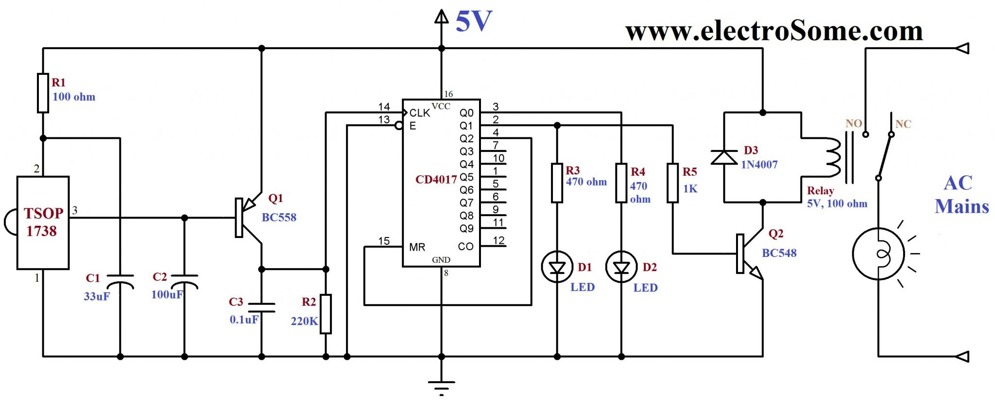
Automatic night lamp as the name suggests is for turning ON and OFF the lamp automatically without the need of human interventions. It senses the light intensity from surroundings and find whether its day or night. And it automatically turns ON when the surrounding is dark and it turns OFF when it receives light from surroundings. A sensor called LDR is used to detect the light intensity. This project finds wide outdoor applications in streets, gardens and public places where...

Transformerless Capacitor Dropper Power Supply

I already posted about transformerless power supplies in the article, Transformerless DC Power Supply. Here we will see how to design a capacitor dropper power supply. Capacitor power supplies are simple, low cost and light weight solution for providing dc supplies to circuits which require low currents. It is low cost and light weight since there is no bulky transformers. Circuit Diagram Transformerless Capacitor Power Supply 12V 40mA The 200mA fuse will protect the circuit from mains during shot circuit or component failures. The 275V...

Simple Electronic Piano using 555 Timer

A simple electronic toy piano can be easily constructed using the popular 555 timer IC. 555 Timer can be easily wired as Astable, Monostable or Bistable multivibrator. We all know that Sound is a Mechanical Wave as it is produced by to and fro movement of particles of the medium. Displacement of particles are in the same direction as propagation of sound waves, so sound is a Longitudinal Wave. The to and fro motion of particles in the medium creates compression...

Interfacing HC-SR04 Ultrasonic Sensor with PIC Microcontroller

HC-SR04 Ultrasonic Distance Sensor is a popular and low cost solution for non-contact distance measurement function. It is able to measure distances from 2cm to 400cm with an accuracy of about 3mm. This module includes ultrasonic transmitter, ultrasonic receiver and its control circuit. HC-SR04 module has 4 pins : VCC - 5V, +ive of the power supply TRIG - Trigger Pin ECHO - Echo Pin GND - -ive of the power supply TRIG and ECHO pins can be used to interface this module with a microcontroller...

Siren Generator using IC UM3561

IC UM3561 is a CMOS LSI IC commonly used in alarm and toy applications. It is able to generate Police Siren, Ambulance Siren, Fire Engine Siren and Machine Gun Sound just by changing simple connections. It is a low cost and low power IC which can work down to 2.4V. We need only a few additional components as this Integrate Circuits has built in oscillator and selector circuits.  About IC UM3561 IC UM3561 - Block Diagram Basic blocks of IC UM3561 are shown...

UM66 Melody Generator – First Step for Electronics Hobbyists

UM66 UM66 is a melody generating IC commonly used in calling bell, phone, toys, musical bell in doors, home security alarm systems, burglar alarms etc. It is a three pin IC looks like a transistor. Its first pin is ground, second is VCC and the third is the melody output. Supply voltage that can be given to the IC is in the range of 1.5V- 4.5V. These are CMOS ICs and have very small power consumption. Melody generator will reset when the...

IR Remote Control for Home Appliances

IR Remote Control for controlling home appliances can be easily made using Decade Counter CD4017, 555 Timer and TSOP1738 infrared receiver. By using this circuit you can easily control your home appliances using your TV, DVD Player remote control or using a remote control circuit described here. Remote Control Receiver Circuit Diagram IR Remote Control for Home Appliances 2nd and 1st pins of TSOP1738 are used to give power, Vcc and Gnd respectively. 100Ω resistor and 33μF capacitor is to suppress power supply...

Dancing Light using 555 Timer

A dancing light can be easily constructed using a 555 timer wired in astable mode. Please read the article Astable Multivibrator using 555 Timer before continuing. This circuit blinks two LEDs alternatively with some delay and it can be easily modified to include more LEDs or for controlling incandescent lamps. Time period of oscillation is determined by RC time constant of the circuit. Circuit Diagram Dancing Light using 555 Timer - Circuit Diagram 1st and 8th pins of 555 timer are used to provide power, Vcc and...

>