

Blinking LED using Atmega32 Microcontroller and Atmel Studio
Contents
Similar to printing ‘Hello World’ in C or C++, the very first step towards programming a microcontroller is Blinking a LED with a delay. Atmega32 is a very popular high performance 8 bit AVR Microcontroller. For this example project we need to use two registers DDR and PORT. DDR stands for Data Direction Register, it determines the direction (Input/Output) of each pins on the microcontroller. HIGH at DDR register makes corresponding pin Output while LOW at DDR register makes corresponding pin Input. PORT register is the output register which determines the status of each pin of a particular port. HIGH at PORT register makes corresponding pin Logic HIGH (5V) while LOW at PORT register makes corresponding pin Logic LOW (0V).
Getting Started with Atmel Studio 6.0
1. Download and Install Atmel Studio. You can download Atmel Studio from Atmel’s Website.
2. Open Atmel Studio

3. Select New Project
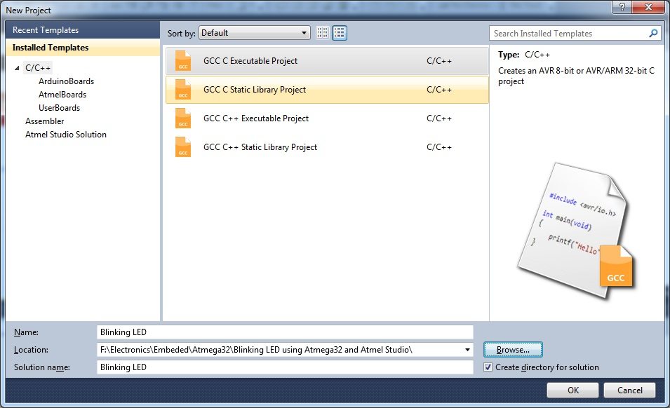
4. Select GCC C Executable Project, give a project name, solution name, location in which project is to be saved and click OK.
5. Selecting Microcontroller
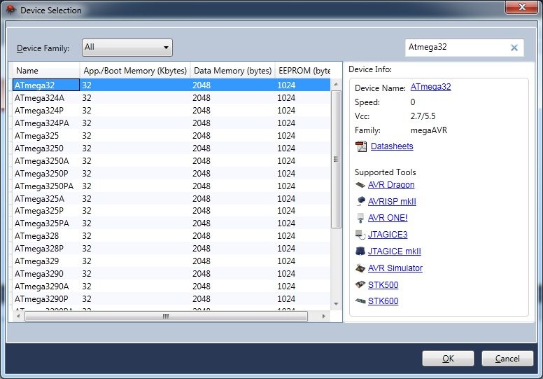
Choose the microcontroller that you are going to use, here we are using Atmega32. Then Click OK.
6. Enter the Program
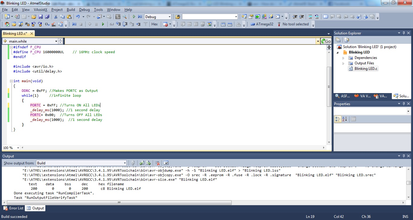
7. Then click on Build >> Build Solution or Press F7 to generate the hex file.
Circuit Diagram
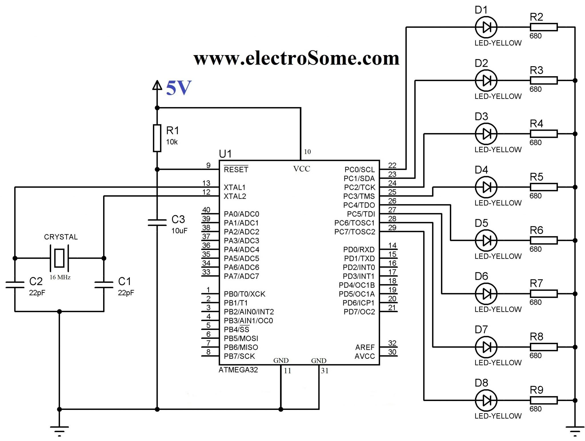
LEDs are connected to PORTC and current limiting resistors are used to limit current through them. 16 MHz crystal is used to provide clock for the Atmega32 microcontroller and 22pF capacitors are used to stabilize the operation of crystal. The 10µF capacitor and 10KΩ resistor is used to provide Power On Reset (POR) to the device. When the power is switched ON, voltage across capacitor will be zero so the device resets (since reset is active low), then the capacitor charges to VCC and the reset will be disabled. 30th pin (AVCC) of Atmega32 should be connected to VCC if you are using PORTA, since it is the supply voltage pin for PORT A.
Atmel Studio C Program
#ifndef F_CPU
#define F_CPU 16000000UL // 16 MHz clock speed
#endif

#include <avr/io.h>
#include <util/delay.h>

int main(void)
{
  DDRC = 0xFF; //Nakes PORTC as Output
  while(1) //infinite loop
  {
    PORTC = 0xFF; //Turns ON All LEDs
    _delay_ms(1000); //1 second delay
    PORTC= 0x00; //Turns OFF All LEDs
    _delay_ms(1000); //1 second delay
  }
}
- DDRC = 0xFF makes all pins on PORTC as output pins
- PORTC = 0xFF makes all pins on PORTC Logic High (5V)
- PORTC = 0x00 makes all pins on PORTC Logic Low (0V)
- _delay_ms(1000) provides 1000 milliseconds delay.
- while(1) makes an infinite loop
You have seen that PORT registers are used to write data to ports. Similarly to read data from ports PIN registers are used. It stand for Port Input Register. eg : PIND, PINB
You may like to set or reset individual pins of PORT or DDR registers or to know the status of a specific bit of PIN register. There registers are not bit addressable, so we can’t do it directly but we can do it through program. To make 3ed bit (PC2) of DDRC register low we can use DDRC &= ~(1<<PC2). (1<<PC2) generates the binary number 00000100, which is complemented 11111011 and ANDed with DDRC register, which makes the 3ed bit 0. Similarly DDRC |= (1<<PC2) can be used set the 3ed bit (PC2) of DDRC register and to read 3ed bit (PC2) we can use PINC & (1<<PC2). Similarly we can set or reset each bit of DDR or PORT registers and able to know the logic state of a particular bit of PIN register.
Proteus Simulation
If you haven’t yet started with PROTEUS, please go to this tutorial. Draw the above circuit in PROTEUS and make following setting on the properties of Atmega32.
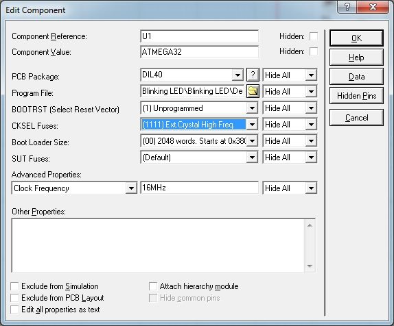
Don’t forget to set the clock frequency to 16 MHz.
You can download the Atmel Studio and Proteus files here…


or crack it 🙂
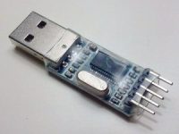
I hope you have learned by know, its connected to the cip via some sort of programmer (many available on market, eg USBASP)
If this looks scary to you, start with arduino , very very easy for beginners.
First of all ,an excellent tutorial. Secondly you didn’t mention why did you use ifndef instead of ifdef? Also what’s the meaning of ifndef?
It’s the same
If I use internal clock 8MHz then how to write
#define F_CPU 16000000UL this line?
Like this #define F_CPU 8000000UL (at the end what UL or L)
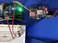
How do i connect computer and microcontroller?
In the other words, how do i connect computer and microcontroller?
How do i program Atmega32 from computer?
Yes, you can use a single resistor if there is only a fixed number of LEDs are turning on at a time.
But if you are modifying something for learning it is good to have separate resistors as the current and voltage will vary depending on the number of LEDs turning on at a time.
would be better to place a resistor in series to the ground instead of placing 8 resistors.
Proteus is not free. You need to buy it from Labcenter Electronics.
Please post the link to download Proteus
very good.
Yes you should reprogram it… no change in circuit..
Can i use the same thing for making the 8 LED blink in squeezes for example :1-8 , 2-7 3-6 etc ? i guess i only have to reprogram it ? am i right ?
Hello, your doubts is not related to above article.
Please use our forums https://electrosome.com/forums/
please help me to get a program to interface gps and gsm with atmega32..
the gps will provide the longitude and latitude always, while pressing a
button the gsm modem receives the data from the gps and will send it to
a particular phone number. please help me.. [email protected]
this is my mail address.. please help me..
good tutorial ….keep it up!