

Interfacing L298N Motor Driver with Arduino Uno
Contents
In this tutorial we will learn how to interface L298N motror driver with Arduino Uno. You might be thinking why we need L298N for controlling a motor. The answer is very simple, Arduino board or a microcontroller IO pins don’t have enough current/voltage driving capability to drive a motor. For driving the motor in both directions (clockwise and anti-clockwise) we need to use an H-Bridge. Please read our article H-Bridge – DC Motor Driving for more information. L298N is an integrated monolithic circuit with dual H-Bridge. It can be used to rotate the motor in both directions and to control the speed of the motor using PWM technique.
Components Required
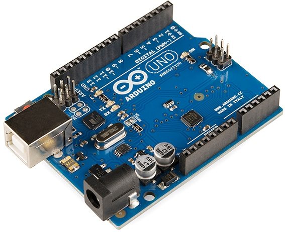
- Arduino Uno
- L298N Motor Driver
- 12V battery
- 2x DC Motors
- Jumper wires
L298N Motor Driver Module

Specifications
- Output A, Output B – To connect two motors.
- Driver Power Input – Board can accept 5V to 35V which will act as the power supply to motor and internal 5V voltage regulator (if it is enabled using jumper).
- GND – Common Ground
- 5V Output / Logic Input Voltage – This pin will give 5V output if the on-board regulator is enabled using the jumper, other we should give the logic supply (5V in the case of Arduino Uno) to this pin.
- IN1, IN2, IN3, IN4 – H-Bridge control inputs which can be used to control direction of motors.
- Enable A and Enable B pins are used for enabling each bridge or for controlling the speed of the motors using PWM.
Working Principle
Here is a simple explanation of H-Bridge motor driving. For more details please read our article, H-Bridge – DC Motor Driving.
H-Bridge consists of 4 MOSFETs or Transistors wired as switches. For easy understanding refer the below circuit with 4 switches. Now let’s imagine, if the switch S1 and S4 are ON we can see that current will flow from left to right direction of the motor. This will make the motor rotate in particular direction, say clockwise.

Similarly if switches S3 and S2 are switched on, the current will flow from right to left, so the motor will rotate in the other direction, say anti-clockwise.

L298N module is having 2 H-Bridge like this. One thing to note in H-Bridge is that we should not switch on S1 and S2 together or S3 and S4 together. This condition is called shoot-through and can damage those MOSFETs or transistors.
Circuit Diagram

Description
- As mentioned above L298N contains two pairs output which are connected to a pair of DC motors.
- The positive of battery is connected to the Power Input of the L298N module and negative is connected to GND.
- The 5V pin of the driver is connected to the Vin pin of the Arduino to power the Arduino board.
- Input 1 and Input 2 pins are used to control the direction of Motor 1 is connected to pin 13, pin 12 of the Arduino respectively.
- Input 3 and Input 4 pins are used to control the direction of Motor 2 is connected to pin 11, pin 10 of the Arduino respectively.
- Enable A and Enable B are connected to the pin 9 and pin 3 of Arduino, which are used to control the speed of motors using PWM.
Program
// Motor A connections
int enA = 9;
int in1 = 13;
int in2 = 12;
// Motor B connections
int enB = 3;
int in3 = 11;
int in4 = 10;

void setup() {
    pinMode(enA, OUTPUT);
    pinMode(enB, OUTPUT);
    pinMode(in1, OUTPUT);
    pinMode(in2, OUTPUT);
    pinMode(in3, OUTPUT);
    pinMode(in4, OUTPUT);

    digitalWrite(in1, LOW);
    digitalWrite(in2, LOW);
    digitalWrite(in3, LOW);
    digitalWrite(in4, LOW);
}

void loop() {
    directionControl();
    delay(1000);
    speedControl();
    delay(1000);
}
void directionControl() {
    // Set motors to maximum speed
    // PWM value ranges from 0 to 255
    analogWrite(enA, 255);
    analogWrite(enB, 255);

    // Turn on motor A & B
    digitalWrite(in1, HIGH);
    digitalWrite(in2, LOW);
    digitalWrite(in3, HIGH);
    digitalWrite(in4, LOW);
    delay(2000);

    digitalWrite(in1, LOW);
    digitalWrite(in2, HIGH);
    digitalWrite(in3, LOW);
    digitalWrite(in4, HIGH);
    delay(2000);

    // Turn off motors
    digitalWrite(in1, LOW);
    digitalWrite(in2, LOW);
    digitalWrite(in3, LOW);
    digitalWrite(in4, LOW);
}
void speedControl() {
    // Turn on motors
    digitalWrite(in1, LOW);
    digitalWrite(in2, HIGH);
    digitalWrite(in3, LOW);
    digitalWrite(in4, HIGH);

    for (int i = 0; i < 256; i++) {
        analogWrite(enA, i);
        analogWrite(enB, i);
        delay(20);
    }

    for (int i = 255; i >= 0; --i) {
        analogWrite(enA, i);
        analogWrite(enB, i);
        delay(20);
    }

    // Now turn off motors
    digitalWrite(in1, LOW);
    digitalWrite(in2, LOW);
    digitalWrite(in3, LOW);
    digitalWrite(in4, LOW);
}
Explanation
- In the setup section all the motor control pins are declared as output and are pulled LOW to make both motors OFF by default.
- In the loop function, two user-defined functions are called within a time delay of one second.
- directionControl() function is defined for rotating both motors in clockwise, anti-clockwise direction and stop for 2 seconds each.
- speedControl() is defined to vary the speed of the motor by varying PWM from 0 to 100% (0 – 255) duty cycle.
Output
Conclusion
Hope you understand about driving DC motor using Arduino Uno and H-Bridge. Please feel free to comment below if you have any doubts.

