

Interfacing EM-18 RFID Module with PIC Microcontroller
Contents
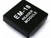
EM-18 RFID Reader Module is the one the most commonly used module for Radio Frequency Identification Projects. It features Low Cost, Small Size, Low Power Consumption and Easy to use. It can be directly interfaced with microcontrollers using UART communication. Software UART can be used for microcontrollers having no UART modules. In this tutorial we will see How to Interface EM-18 RFID Reader Module with PIC 16F877A Microcontroller. By understanding the basic idea, you will be able to interface it with any microcontrollers.
Working of RFID
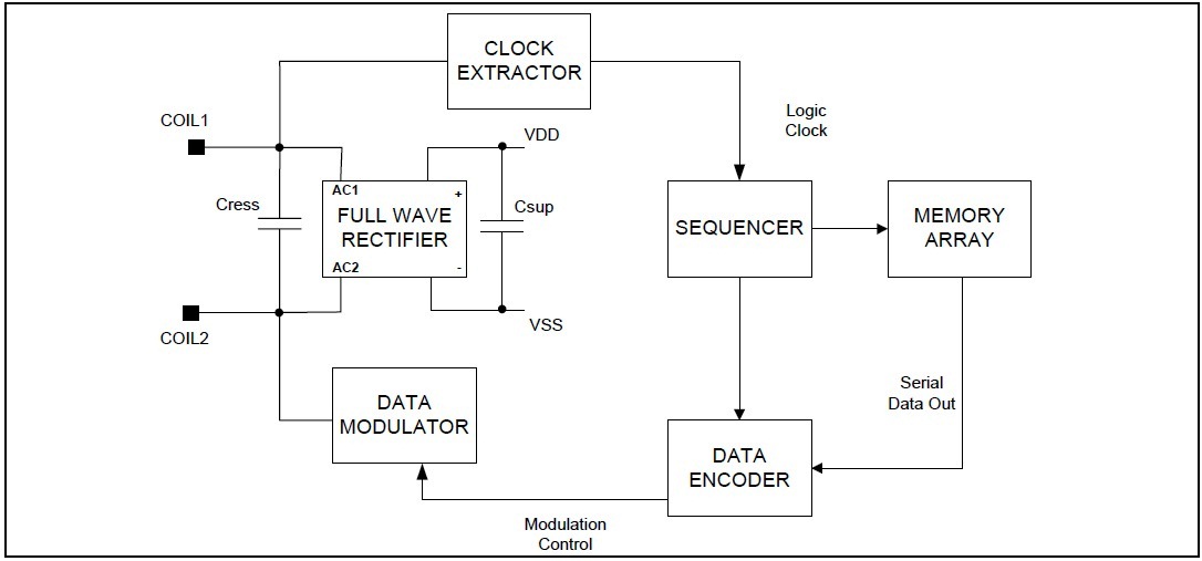
The EM-18 RFID Reader module generates and radiates RF Carrier Signals of frequency 125KHz through its coils. When a 125KHz Passive RFID Tag (have no battery) is brought in to this field, will get energized from it. These RFID Tags are usually made using a CMOS IC EM4102. It gets enough power and master clock for its operations from the electromagnetic fields produced by RFID Reader.

By changing the modulation current through the coils, tag will send back the information contained in the factory programmed memory array.
Interfacing with PIC Microcontroller
EM-18 RFID Reader Module can be directly interfaced with 5V PIC Microcontrollers using UART module. For 3.3V devices you need to add additional voltage divider resistors to reduce 5V to 3.3V. You may also use Software UART if a dedicated UART module is not available.
When a RFID Tag is bring in to the field of EM-18 RFID Reader, it will read its tag number and give output via TX terminal. The BEEP terminal will become LOW to indicate valid tag detection. The UART output will be 12 ASCII data, among these first 10 will be tag number and last 2 will be XOR result of the tag number which can be used for error testing.
For eg : If the RFID tag number is 500097892E, output of EM-18 Reader will be 500097892E60 where 60 is 50 xor 00 xor 97 xor 89 xor 2E.
Circuit Diagram

0.1uF, 10uF, 100uF capacitors are for filtering power supply. Note that TX of RFID Reader is connected to the RX of microcontroller. When a 125KHz RFID tag is bring in to the filed of Reader Module, BEEP terminal becomes low. This will turns on the Buzzer and LED. Meantime RFID tag data will be send to microcontroller via UART.
Programming
MikroC Pro Code
// LCD module connections
sbit LCD_RS at RB2_bit;
sbit LCD_EN at RB3_bit;
sbit LCD_D4 at RB4_bit;
sbit LCD_D5 at RB5_bit;
sbit LCD_D6 at RB6_bit;
sbit LCD_D7 at RB7_bit;

sbit LCD_RS_Direction at TRISB2_bit;
sbit LCD_EN_Direction at TRISB3_bit;
sbit LCD_D4_Direction at TRISB4_bit;
sbit LCD_D5_Direction at TRISB5_bit;
sbit LCD_D6_Direction at TRISB6_bit;
sbit LCD_D7_Direction at TRISB7_bit;
// End LCD module connections

void main()
{
 char i, rfid[13];
 Lcd_Init();                       // Initialize LCD
 Lcd_Cmd(_LCD_CLEAR);              // Clear display
 Lcd_Cmd(_LCD_CURSOR_OFF);         // Cursor off
 Lcd_Out(1,1,"RFID Tag Reader");   // Write text in first row

 UART1_Init(9600);                 // Initialize UART, 9600 baud rate

 rfid[12] = '\0';                  // String Terminating Character

 while(1)                          // Infinite Loop
 {
   if(UART1_Data_Ready())          // If UART Data Ready
   {
     for(i=0;i<12;)                // To Read 12 characters
     {
       if(UART1_Data_Ready())
       {
         rfid[i] = UART1_Read();
         i++;
       }
     }
     // Check For Errors
     if((rfid[0] ^ rfid[2] ^ rfid[4] ^ rfid[6] ^ rfid[8] == rfid[10]) && (rfid[1] ^ rfid[3] ^ rfid[5] ^ rfid[7] ^ rfid[9] == rfid[11]))
     {
       Lcd_Out(2,1,rfid);
     }
     else
     {
       Lcd_Out(2,1,"Error ");
     }
   }
 }
}
You should be familiar with our MPLAB XC8 LCD Library and MPLAB XC8 UART Library before understanding following program.
MPLAB XC8 Code
#define _XTAL_FREQ 8000000

// LCD Module Connections
#define RS RB2
#define EN RB3
#define D4 RB4
#define D5 RB5
#define D6 RB6
#define D7 RB7
// END LCD Module Connections

#include <xc.h>
#include "lcd.h";
#include "uart.h";
#include <pic16f877a.h>

// BEGIN CONFIG
#pragma config FOSC = HS // Oscillator Selection bits (HS oscillator)
#pragma config WDTE = OFF // Watchdog Timer Enable bit (WDT enabled)
#pragma config PWRTE = OFF // Power-up Timer Enable bit (PWRT disabled)
#pragma config BOREN = ON // Brown-out Reset Enable bit (BOR enabled)
#pragma config LVP = OFF // Low-Voltage (Single-Supply) In-Circuit Serial Programming Enable bit (RB3 is digital I/O, HV on MCLR must be used for programming)
#pragma config CPD = OFF // Data EEPROM Memory Code Protection bit (Data EEPROM code protection off)
#pragma config WRT = OFF // Flash Program Memory Write Enable bits (Write protection off; all program memory may be written to by EECON control)
#pragma config CP = OFF // Flash Program Memory Code Protection bit (Code protection off)
//END CONFIG

void main()
{
  char i,rfid[13];

  TRISB = 0x00;                        // PORTB as Output, to connect LCD

  Lcd_Init();                          // Initialize LCD
  Lcd_Clear();                         // Clear display
  Lcd_Set_Cursor(1,1);
  Lcd_Write_String("RFID Tag Reader"); // Write text in first row

  UART_Init(9600);                     // Initialize UART, 9600 baud rate

  rfid[12] = '\0';                     // String Terminating Character

  while(1)
 {
   if(UART_Data_Ready())
   {
     for(i=0;i<12;)
     {
       if(UART_Data_Ready())
       {
         rfid[i] = UART_Read();
         i++;
       }
     }
     // Checking for Errors
     if((rfid[0] ^ rfid[2] ^ rfid[4] ^ rfid[6] ^ rfid[8] == rfid[10]) && (rfid[1] ^ rfid[3] ^ rfid[5] ^ rfid[7] ^ rfid[9] == rfid[11]))
     {
       Lcd_Set_Cursor(2,1);
       Lcd_Write_String(rfid);
     }
     else
     {
       Lcd_Set_Cursor(1,1);
       Lcd_Write_String("Error ");
     }
   }
  }
}
Note : You should include header files “lcd.h” and “uart.h” to the project directory before building the project. For more details please read the following tutorials.
- Interfacing LCD with PIC Microcontroller – MPLAB XC8
- Using UART Module of PIC Microcontroller – MPLAB XC8
Hope you can understand the program as it is well commented. If you have any doubts, just comment below.
Download
You can download entire project files here.
- Interfacing EM-18 RFID Reader Module with PIC Microcontroller – MikroC Pro
- Interfacing EM-18 RFID Reader Module with PIC Microcontroller – MPLAB XC8


Hi Manvitha,
Sorry for the late response. It is quite hard to tell the problem without further debugging. If you have a USB/UART device, try monitoring what is happening in the UART lines.
Hello sir,in my hardware the ,on lcd is showing “rfid tag reader”.
But the em 18 reader module is not scanning the cards ,I mean led and buzzer are also not responding and lcd is not displaying the number, can u tell what is the problem
Yes it will work for RS232 also.
hello gentlemen
Please I need some help. Can this program be used for Rs232 instead of Em_18 as card reading and what is required of the program by Both softwares where MickroC is good enough cordially remichi Zohra
In my opinion you should learn C, baisc is outdated.
You made it with MikroC, which is from the same company like Mikrobasic – Mikroelektronika. Do you know anybody who can do it? I can pay for this small job. I want to develop more around the code, but i do not know C. For this size of code , Mikrobasic is free.
https://www.mikroe.com/mikrobasic-pic.
Thanks for the feedback. Sorry I don’t have any idea about Mikrobasic.
Works like a charm.
Can you convert it to Mikrobasic Pro for the same Pic?
Thank you
NFC is different from RFID
I have developed a similar project before few years. It is connected with a computer software. If you like I can share the details. Drop me a mail [email protected]
sorry, but i want to know if you have finished your pic coding and you can send it to me please?
I am cuurently working on a gate access system using RFID module and Tag and PIC 16f77. I just need the detection of the card as an output using which i will open up the Gate. Would I need a UART program for that? If not how else can i retrieve the output. Would be grateful if you help me with this .
Hello sir, I have to make a NFC reader, which can recognize my android phone from others. I should use PN532 and PIC16f. Is it the same principle and similiar as you did in this project? I am a student and that is my school project. Thank you very much in advance. Sergey
im using pic 16f877a
can we connect 2 rfid readers (em 18 ) in the same pic???
Hello Sir! Thanks for the tutorial. I am having PIC18F4550 instead of PIC16F. I have done the required changes in the code but I am getting values like “/+=/+=/+=/+=” in the LCD. The garbage value displayed is the same every time for a card. Can you tell where I am going wrong?
Please use our forums ( https://electrosome.com/forums/ ) for asking doubts outside the scope of above article.
Hello Ligo..
Need your help for the GSM SIM900 Module with PIC Controller.
Can you Give me any suggestion ?
It won’t show same data for all cards. It will disply the code of that particular card only. I don’t know whether you are using 125KHz card or no. EM-18 works only with 125KHz cards.
You need to write codes for it.
Hello Ligo Sir,
I done the same thing as above BUT now its take number but only showing ‘6’ digit for all card. So lease tell me solution for that
As per your code… Once Tag is detected, All time, its displaying RFID, that’s all.
So… how can we understand whether tag is correct or not..
Thanks in advance!!
Just display it and see what data your tag is giving.
Hi Ligo,
Can you just tell me when this tag will give error? because for me, its detecting all RFID tag…
You mean LCD displaying “Error ” ??
I didn’t simulated above project, only tested in hardware.
Hi Ligo i tried the same code and every time it gives ERROR displayed on LCD
May I know what simulation tool did you use in creating the circuit diagram?
Some applications we need to interface with PIC.
Plzzzz hep…
Why we are interacing reader to pic??….if we can directly connect reader to pc…..need of pic
What ?
So we can made it or where we can find it
It is not there in proteus.
Hello,
I am sorry, We cannot provide this kinds of project development freely. As you know it is impossible for us to develop project for each and everyone free of cost. If you need it, please hire one of our engineers and pay for it. It will help us to live.
sir..how to find em18 rfid reader module in proteus??
Thanks sir! for a very powerful article, I need you are help am designing rfid car parking system and payment management,simply once the car enter in a parking lot, rfid reader detect the valid tag from the car and send the signal to trigger microcontroller pic 16f877a. to start count timespent in the parking lot, and it calculate cost according to time spent on lot and send the information to database (tag id, time, and costAnd the system will have a gsm module to send txt to client about cost and time..If the tag is not valid the system will alert by using buzzer all the user will be registered. ……
I need ur help on how to design a circuit and source code using proteus and micro C
Above program is 100% working. It is for EM-18 RFID reader module. It might not work for other readers.
hello Sir, your article above is very helpful. but am having issues with the code. when i tried out the code on my hardware. it displays weird first character on the lcd. i’ve tried my best to detect what could be the cause but still cannot fix it. please help. Thanks
Why should you need to add customer details to the card ? There will be unique identification number for each cards. You can save those details to database corresponding to the unique id of the card.
You need to write the program to PIC Microcontroller.
I am going to do a Automatic Ration shop using a RFID card and GSM.Can i add a customer details into this card?
I am new to using RFID .And this program upload into what?
You can use the project files above. Use the same program. It will work in proteus.
What do you meant by tts component ?
Most of the tags available in the market are read only. There are writable tags. You can write your own code in those using a RFID writer.
Thanks a lot. I got the output
dear sir,
is it possible to interface along with these components( i.e. PIC 16f877A, rfid module and lcd display), a tts component…and can we substitute the entire rf tag number as a character like A or something and then display it as some string characters….
expecting an early reply..
sir can you provide project files to interface rfid with pic in proteus (using virtual terminal as rfid)?
Don’t you read above article ? It is clearly mentioned there.
Last two bytes are checksum for error detection. So it just checks whether the data is correct or not.
Hi ligo I have a small doubt why you have use this condition…..if((rfid[0] ^ rfid[2] ^ rfid[4] ^ rfid[6] ^ rfid[8] == rfid[10]) && (rfid[1] ^ rfid[3] ^ rfid[5] ^ rfid[7] ^ rfid[9] == rfid[11]))
Answers :
1. Your board has voltage regulator IC, so you can provide input from 9V to 15V.
2. If you want to use RS232, you should use MAX232 IC. But your board has TTL output pins. So it is better to use it. Or you can even unplug the EM-18 module from the PCB
3. Better you try to unplug the EM-18 (black square box) from the PCB, then you will understand all.
Sir I am new to this, I want your help in clearing my doubt.I have bought EM-18 Rfid reader module(complete board).But my reader contains pin as RS232 in place of Tx as as shown here.Sir my doubt are,
1)My RFID reader contain DB9 and DC connection for 9-15V,can it be worked using either one?
2)Is RS232 pin is same as Tx(did they do that by mistake?)
3)Pin available for me are GND,RS232,BEEP,WDATA0,WDATA1.So sir to do above project I need to use GND,RS232,BEEP and one power supply?
My question may look stupid to you ,but I need help sir?
thank you very much for the quick reply sir, now i can (probably) go through with my project!
1. Range of EM-18 RFID reader is about 10cm
2. Yes, you need to program it.
3. You can program any of the IO pin as Output.
4. Yes,
6. Yes, only 1 PIC is required.
thanks sir for the tutorial, actually planning to make a rfid based password system, like i want to ask some questions sir
1) what is the range of the reader? like 1 inch?
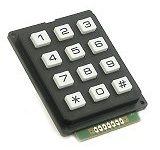
2) can i also put a 4*3 matrix for manual password incase the tag is not available?
3) also, which pin serves an output of “1” if the tag(rfid) or password(matrix) correct?
4) can i also connect a servo ?
5) lastly, are all this possible to connect with just 1 PIC or do i need more?
thank you sir, please reply 🙂
Great tutorial, the best there i could find
There is no EM-18 in proteus, so you should try it in real hardware.
hello sir, Can u please tell me that how can we test the circuit by simulation in Proteus, Coz i couldn’t find EM-18 sensor in proteus.
use terminal v1.9b
Thanks for the info. It is corrected now.
thnks sir for the great help
this code missses a clossing bracket for main function
Above programes are tested and verified in hardware.. It is working fine.
sir, after power on, only first time it reads the tag correctly ,when we again use the tag it shows incorrect tag no. it miss last two bytes in display…i have downloaded your code…pls check it
thanks….always for your support….i have learnt many things from electrosome…
Sorry, I haven’t yet used rfid reader v7.0. Kindly check the datasheet of your reader.
helo sir… thank u for this code it works really well…. i had one small, stupid doubt…. that if we use rfid reader v7.0 instead of em-18 reader…. will that make any difference??
Please use our forums (https://electrosome.com/forums) for asking doubts not related to above article.
can you help me pic16f877a interfacing with FIM3030 code
Try once more… make sure that connection TX to RX is correct…
I tried it with PL2303 USB to UART, it worked without any problem..
What PULL UP resistor ??
You may use the following method to separate first 10 bytes..
…….
……..
char tag[11];
………
……….
tag[10] = ”;
………….
…………..
for(i=0;i<10;i++)
tag[i] = rfid[i];
Print tag
thanks buddy. did you enable pull up resistor?
how can I separate first 10 number from last 2 XOR?
Sorry, it is rfid[12]=” … .It was an HTML mistake… Now corrected..
Thanks..
thanks sir for this nice tutorial, i want to use why you use
rfid[12] = ”; // String Terminating Character