

Interfacing Mercury Tilt Switch with Arduino Uno
Contents
In this tutorial we will learn how to interface Tilt Sensor with Arduino Uno. As the name suggests, it is an electronic device used to detect the orientation or tilting of an object and provides digital output based on the orientation. It behaves like a normal ON – OFF switch that is controlled by tilting. Tilt sensor consists of a mercury ball and two contacts in a sealed enclosure, in which the mercury ball will short the leads based on the orientation.
Components Required
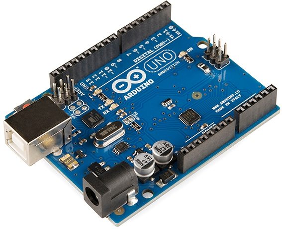
- Arduino Uno
- Tilt Sensor
- LED
- 220Ω Resistor
- Buzzer
- Bread Board
- Jumper Wires
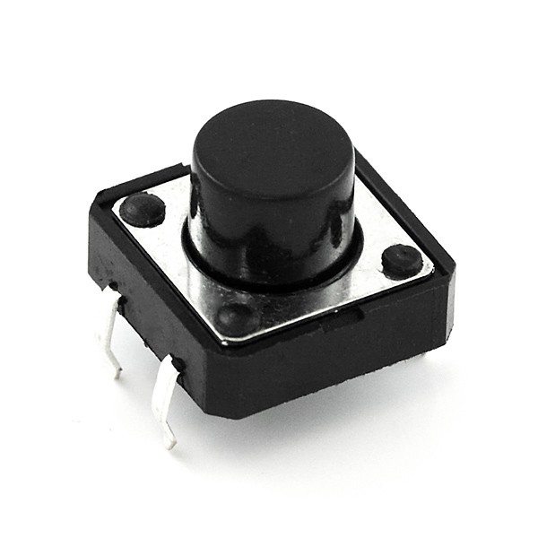
Mercury Tilt Sensor

Specifications
- Tilt sensor consists of 3 pins : GND, VCC, DO (Output Signal)
- Operating Voltage : 3.3 V to 5 V
- Maximum output current : 15mA
Working
Not Tilted
When the sensor is in “Not Tilted” position, the mercury ball will be at the bottom and shorting the contacts as shown in the image below. This will turn ON the LED and the output will be LOW.

Tilted
When the sensor is in “Tilted” position, the mercury ball will move away from the contacts as shown in the image below. This will turn OFF the LED and the output will be HIGH.

Circuit Diagram

Description
- The GND pin of tilt sensor – GND pin of Arduino Uno.
- The VCC pin of tilt sensor – 5V pin of Arduino Uno.
- The output pin of tilt sensor – pin 2 of Arduino Uno.
- The positive pin of the buzzer – pin 3 of Arduino Uno
- The negative pin of the buzzer – the GND.
- The positive pin of the LED – pin 13 of Arduino Uno
- The negative pin of the LED – GND
Program
void setup() {
    pinMode(13, OUTPUT);
    pinMode(3, OUTPUT);
    pinMode(2, INPUT);
}
void loop() {
    if (digitalRead(2) == 1)
    {
        digitalWrite(13, HIGH);
        digitalWrite(3, HIGH);
        delay(300);
        digitalWrite(13, LOW);
        digitalWrite(3, LOW);
        delay(300);
    }
}
Code Explanation
- Pin 2 and pin 3 are defined as output pins for LED and Buzzer respectively.
- Pin 2 is defined as input to read the Tilt Switch status.
- When the tilt sensor is inclined beyond a particular angle, it’s output goes HIGH. Which is read continuously in the infinite loop.
- When the pin 2 is read HIGH, it is programmed to turn ON and OFF both LED and Buzzer alternatively with some delay.
Output
Conclusion
I hope that you understood about the tilt switch and how to interface it with Arduino Uno. Please feel free to modify the circuit or code as per you needs. For any doubts, comment box is always open below.


