

Interfacing Stepper Motor with 8051 using Keil C – AT89C51
Contents
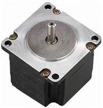
A Stepper Motor is a brushless, synchronous DC Motor. It has many applications in the field of robotics and mechatronics. The total rotation of the motor is divided into steps. The angle of a single step is known as the stepper angle of the motor. There are two types of stepper motors Unipolar and Bipolar. Due to the ease of operation unipolar stepper motor is commonly used by electronics hobbyists. For more details please read the article Stepper Motor or Step Motor. Stepper Motors can be easily interfaced with a microcontroller using driver ICs such as L293D or ULN2003.
Driving Unipolar Stepper Motor with 8051
Unipolar stepper motors can be used in three modes namely the Wave Drive, Full Drive and Half Drive mode. Each drive have its own advantages and disadvantages, thus we should choose the required drive according to the application and power consumption.
Wave Drive
In this mode only one electromagnet is energized at a time. Generated torque will be less when compared to full drive in which two electromagnets are energized at a time but power consumption is reduced. It has same number of steps as in the full drive. This drive is preferred when power consumption is more important than torque. It is rarely used.
| Wave Drive Stepping Sequence | ||||
|---|---|---|---|---|
| Step | A | B | C | D |
| 1 | 1 | 0 | 0 | 0 |
| 2 | 0 | 1 | 0 | 0 |
| 3 | 0 | 0 | 1 | 0 |
| 4 | 0 | 0 | 0 | 1 |
Full Drive
In this mode two electromagnets are energized at a time, so the torque generated will be larger when compared to Wave Drive. This drive is commonly used than others. Power consumption will be higher than other modes.
| Full Drive Stepping Sequence | ||||
|---|---|---|---|---|
| Step | A | B | C | D |
| 1 | 1 | 1 | 0 | 0 |
| 2 | 0 | 1 | 1 | 0 |
| 3 | 0 | 0 | 1 | 1 |
| 4 | 1 | 0 | 0 | 1 |
Half Drive
In this mode alternatively one and two electromagnets are energized, so it is a combination of Wave and Full drives. This mode is commonly used to increase the angular resolution of the motor but the torque will be less, about 70% at its half step position. We can see that the angular resolution doubles when using Half Drive.
| Half Drive Stepping Sequence | ||||
|---|---|---|---|---|
| Step | A | B | C | D |
| 1 | 1 | 0 | 0 | 0 |
| 2 | 1 | 1 | 0 | 0 |
| 3 | 0 | 1 | 0 | 0 |
| 4 | 0 | 1 | 1 | 0 |
| 5 | 0 | 0 | 1 | 0 |
| 6 | 0 | 0 | 1 | 1 |
| 7 | 0 | 0 | 0 | 1 |
| 8 | 1 | 0 | 0 | 1 |
Now we will see how to implement these drives.
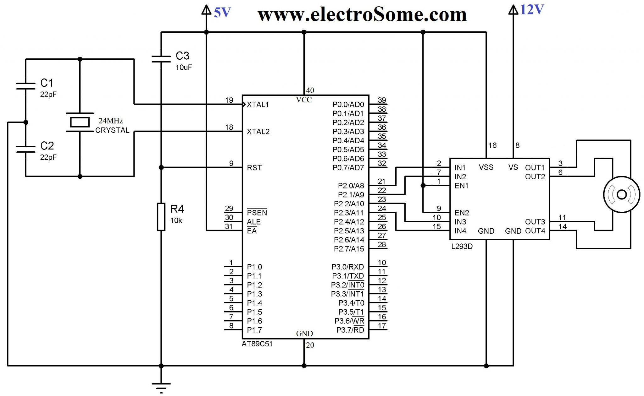
Interfacing Using L293D
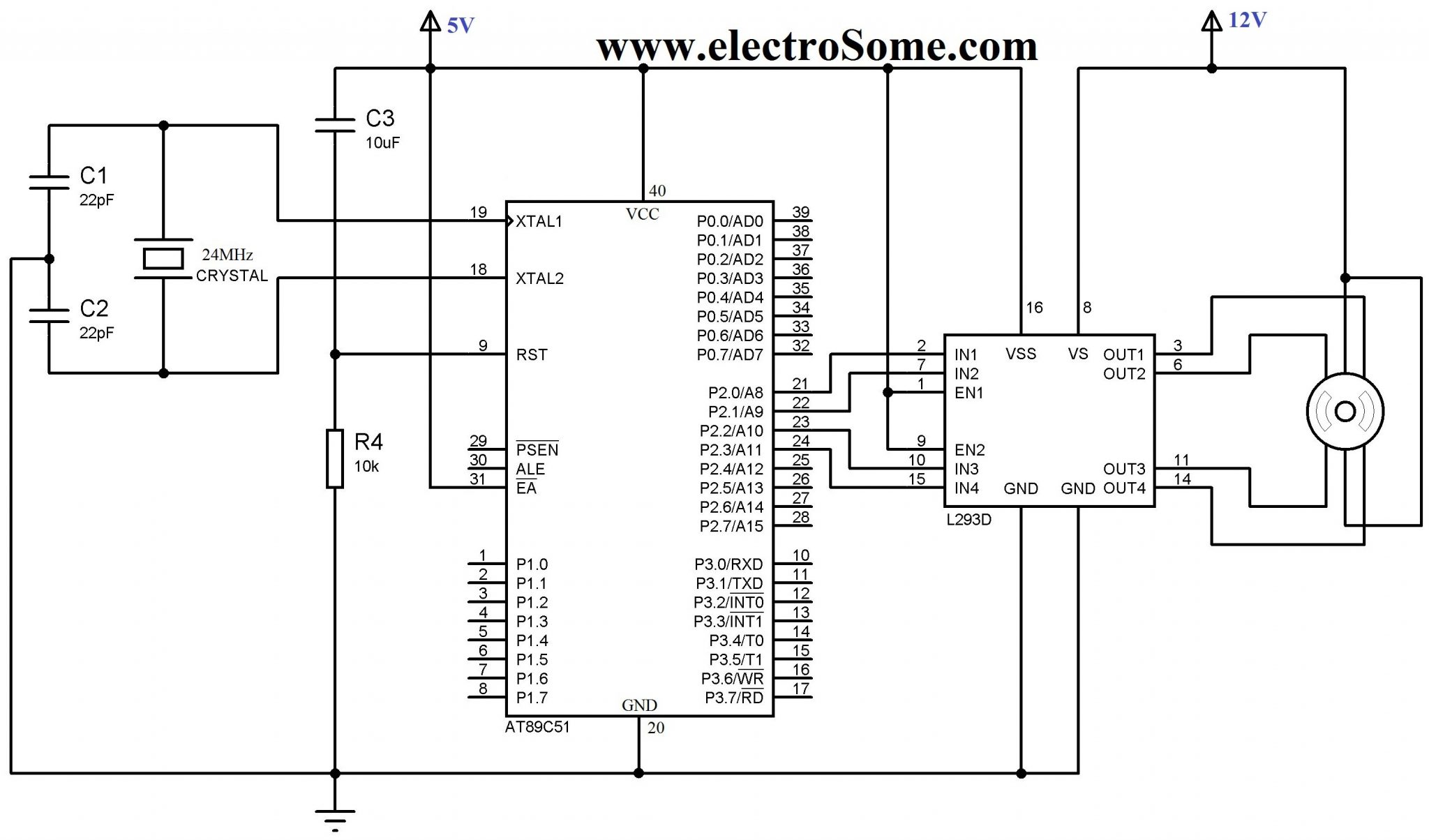
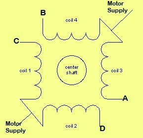
This is the circuit diagram of driving a bipolar stepper motor using 8051 microcontroller using L293D. 24MHz crystal is connected to provide the required clock for the microcontroller. 10μF capacitor and 10KΩ is used to provide Power On Reset (POR) for the 8051 microcontroller. L293D is connected to pins P2.0, P2.1, P2.2, P2.3 of the microcontroller and two pairs of L293D are enabled by tieing EN1, EN2 to 5V. Logic Voltage (5V) is connected to Vss pin and Motor Supply (12V) is connected to the Vs pin of L293D. Center Tap of each windings of stepper motor is shorted and connected to the motor supply. Now we can energize each winding of the motor by making corresponding pin of L293D LOW.
Interfacing Using ULN2003
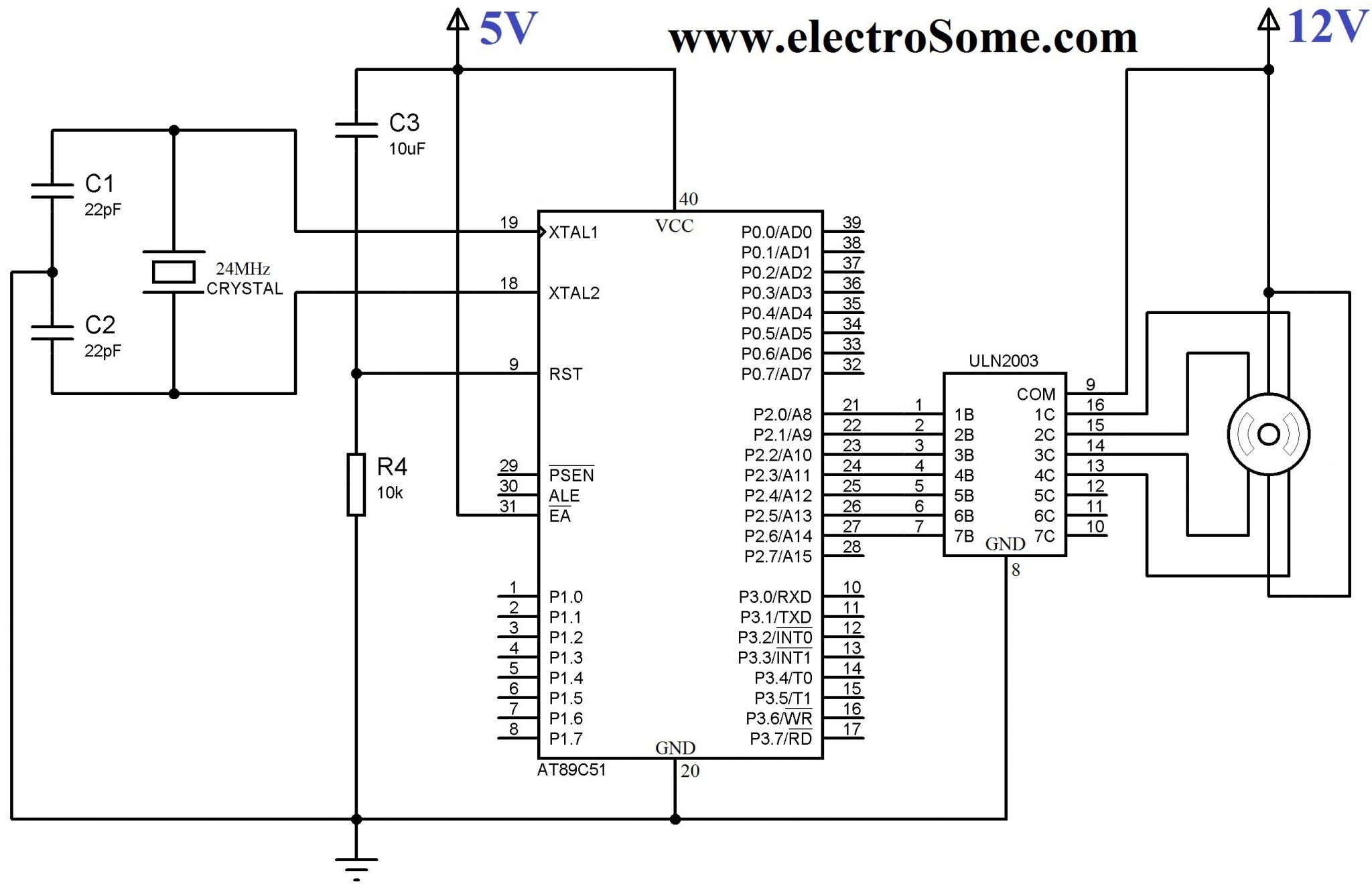
In this circuit instead of L293D, ULN2003 is used. Working is similar to the previous circuit, when an input (say 1B) is HIGH corresponding output pin (1C) will be grounded. Thus we can energize any winding of stepper motor.
Keil C Code For Wave Drive
#include<reg52.h>
#include<stdio.h>

void delay(int);

void main()
{
  do
  {
    P2=0x01; //0001
    delay(1000);
    P2=0x02; //0010
    delay(1000);
    P2=0x04; //0100
    delay(1000);
    P2=0x08; //1000
    delay(1000);
  }
while(1);
}

void delay(int k)
{
  int i,j;
  for(i=0;i<k;i++)
  {
    for(j=0;j<100;j++)
    {}
  }
}
Keil C Code for Full Drive
#include<reg52.h>
#include<stdio.h>

void delay(int);

void main()
{
  do
  {
    P2 = 0x03; //0011
    delay(1000);
    P2 = 0x06; //0110
    delay(1000);
    P2 = 0x0C; //1100
    delay(1000);
    P2 = 0x09; //1001
    delay(1000);
  }
while(1);
}

void delay(int k)
{
  int i,j;
  for(i=0;i<k;i++)
  {
    for(j=0;j<100;j++)
    {}
  }
}
Keil C Code for Half Drive
#include<reg52.h>
#include<stdio.h>

void delay(int);

void main()
{
  do
  {
    P2=0x01; //0001
    delay(1000);
    P2=0x03; //0011
    delay(1000);
    P2=0x02; //0010
    delay(1000);
    P2=0x06; //0110
    delay(1000);
    P2=0x04; //0100
    delay(1000);
    P2=0x0C; //1100
    delay(1000);
    P2=0x08; //1000
    delay(1000);
    P2=0x09; //1001
    delay(1000);
  } while(1);
}

void delay(int k)
{
  int i,j;
  for(i=0;i<k;i++)
  {
    for(j=0;j<100;j++)
    {}
  }
}
You can simplify these codes using the shift (<< >>) operators in C.
Interfacing Bipolar Stepper Motor
Bipolar stepper motors have no center tap and having equal coil resistances. It can be easily interfaced with a microcontroller using L293D DC Motor Driver IC.
Circuit Diagram
Keil C Code
#include<reg52.h>
#include<stdio.h>

void delay(int);

void main()
{
  do
  {
    P2=0x01; //0001
    delay(1000);
    P2=0x04; //0100
    delay(1000);
    P2=0x02; //0010
    delay(1000);
    P2=0x08; //1000
    delay(1000);
  }while(1);
}

void delay(int k)
{
  int i,j;
  for(i=0;i<k;i++)
  {
    for(j=0;j<100;j++)
    {}
  }
}
You can download Keil C files and Proteus files here…


Kindly use our forums ( https://electrosome.com/forums/ ) for asking doubts outside the scope of above article.
You can contact us if you need premium support.
Design 8051/PIC microcontroller based system for control of ROBOT arm in 90°clockwise direction and 90° anticlockwise direction. The direction if ROBOT arm is control by a key. Stepper motor is having teeth’s having a step angle of 1.8°. Find out the number of steps required for rotating 90°. Draw appropriate interface circuitry flow chart and write a program to drive the motor through with a delay of .5 sec (500 ms)..
Pls Can i get the program for above question
Hello sir my project is vehicle accident detection using gsm and gps. I want coading of gps reciver modem. I am using 89c51 microcontroller .I want code in embedded c. Plz help me sir
You can easily manage using Microcontroller programming
Can anyone help me to drive this bipolar motor through external switch?
i used the the same circuit with l293d and 8051 and i used similar program for full drive.
but i didn’t get the rotation,the motor is just vibrating or it just deflects a couple of degrees,i have tried all 24 combinations of inputs to motor thinking that the motor position and the program should synchronize,but it didn’t solve.
what might be the problem??
please send me the program for 3steps per revolution in a stepper motor.
i want to interface synchronous motor with 89c51.. what type of driver circuit should be used for runnig a synchronous motor..
i want to put 4 push button as start,stop,clockwise and anticlokwise. but i got some problem how to trigger the pin to ensure that stepper motor follow the push button. if using dc motor it more simple just in1=0 and in2=0 to stop the motor and vice versa.can u give some idea??thank you.
thanks
It depends upon the current rating of motor…I think ULN2003 can drive upto 1A… so maximum current limit of motor is 1A..
Hw big a stepper motor can be used with uln2003