

Using UART of PIC Microcontroller – MPLAB XC8
Contents
UART stands for Universal Asynchronous Receiver / Transmitter. It is a very popular serial communication interface which provides Full Duplex communication between two devices. UART uses two data lines for sending (TX) and receiving (RX) data. Ground/Reference of both devices should be made common. As the name indicates it is an asynchronous communication interface, which means that it doesn’t need to send CLOCK along with data as in synchronous communications. UART is the communication interface used by our old computer’s RS-232 port.
Some of the Microchip’s PIC Microcontroller has built in USART Module. USART stands for Universal Synchronous Asynchronous Receiver Transmitter and it can be configured in following modes.
- UART – Asynchronous (Full Duplex)
- USRT Master – Synchronous (Half Duplex)
- USRT Slave – Synchronous (Half Duplex)
In this tutorial we will learn how to use UART Mode of USART Module using MPLAB XC8 Compiler. For demonstration we are using PIC 16F877A microcontroller.
PIC 16F877A USART Module
USART Registers
TXSTA – Transmit Status and Control Register
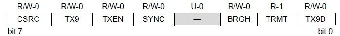
- Bit 0 TX9D : This is the 9th bit of data in the 9 bit transmission mode which is commonly used as a Parity Bit.
- Bit 1 TRMT : This is the Transmit Shift Register (TSR) status bit. This can be used to check whether the data written to transmit register is transmitted or not. When the TRS is empty this bit is set and when the TSR is full this bit will be 0.
- Bit 2 BRGH : This is the High Baud Rate Select bit for Asynchronous mode operation and is unused in Synchronous mode. Setting this bit selects High Speed and clearing this bit selects Low Speed baud rates. You will can see the baud rate calculation later in this article.
- Bit 3 Unimplemented : This bit is unimplemented and will read as 0.
- Bit 4 SYNC : This is the USART Mode select bit. Setting this bit selects Synchronous mode while clearing this bit selects Asynchronous mode.
- Bit 5 TXEN : Setting this bit enables the transmission. In the synchronous mode operation CREN and SREN bits of RCSTA register overrides this bit.
- Bit 6 TX9 : When this bit is set it enables the 9 bit transmission otherwise 8 bit transmission is used. 9th bit in the 9 bit transmission mode is commonly used as parity bit.
- Bit 7 CSRC : Clock Source Select Bit, this bit has no application in the Asynchronous mode operation of USART module. It is used to select master or slave mode in Synchronous mode operation.
RCSTA – Receive Status and Control Register

- Bit 0 RX9D : This is the 9th bit of Received Data and is commonly used as Parity Bit.
- Bit 1 OERR : Overrun Error bit. A high at this bit indicates that Overrun error has occured.
- Bit 2 FERR : Framing Error bit. 1 at this bit stands for Framing Error while 0 stands for No Framing Error.
- Bit 3 ADDEN : Address Detect Enable bit. This bit is applicable only in Asynchronous 9 bit mode. Setting this bit enables Address Detect.
- Bit 4 CREN : Continuous Receive Enable bit. Setting this bit will enable Continuous Receive. In the Synchronous Mode CREN overrides SREN.
- Bit 5 SREN : Single Receive Enable bit. This bit has no effect on Asynchronous mode and Synchronous Slave mode. Setting this bit will enables Single Receive. This bit will cleared after the reception is complete.
- Bit 6 RX9 : Setting this bit enables 9 bit reception otherwise it will be in 8 bit reception mode.
- Bit 7 SPEN : Serial Port Enable bit. Setting this bit enables serial port and configures RC7, RC6 as serial port pins.
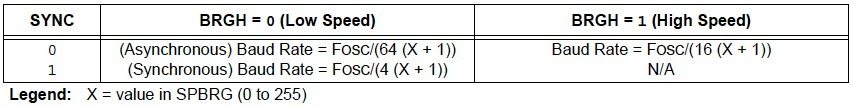
USART Baud Rate Generator (BRG)
Baud Rate Generator provides the required clock for the data transmission and reception. USART module has a dedicated 8 bit baud rate generator which supports both Synchronous and Asynchronous modes. The 8-bit SPBRG register controls the time period of this free running timer. In Asynchronous mode BRGH, 2nd bit of TXSTA register also controls the generated baud rate but in Synchronous mode it is ignored. Baud Rate can be calculated from the following equations, where FOSC is the clock frequency of the microcontroller.
MPLAB XC8 Programming
Initializing UART
char UART_Init(const long int baudrate)
{
  unsigned int x;
  x = (_XTAL_FREQ - baudrate*64)/(baudrate*64);   //SPBRG for Low Baud Rate
  if(x>255)                                       //If High Baud Rage Required
  {
    x = (_XTAL_FREQ - baudrate*16)/(baudrate*16); //SPBRG for High Baud Rate
    BRGH = 1;                                     //Setting High Baud Rate
  }
  if(x<256)
  {
    SPBRG = x;                                    //Writing SPBRG Register
    SYNC = 0;                                     //Setting Asynchronous Mode, ie UART
    SPEN = 1;                                     //Enables Serial Port
    TRISC7 = 1;                                   //As Prescribed in Datasheet
    TRISC6 = 1;                                   //As Prescribed in Datasheet
    CREN = 1;                                     //Enables Continuous Reception
    TXEN = 1;                                     //Enables Transmission
    return 1;                                     //Returns 1 to indicate Successful Completion
  }
  return 0;                                       //Returns 0 to indicate UART initialization failed
}
Note : 6th and 7th bit of TRISC registers are set as prescribed in the datasheet.
Sending Data Through UART
Writing a Character
void UART_Write(char data)
{
  while(!TRMT);
  TXREG = data;
}
Checking Transmit Register
char UART_TX_Empty()
{
  return TRMT;
}
Writing Text
void UART_Write_Text(char *text)
{
  int i;
  for(i=0;text[i]!='\0';i++)
    UART_Write(text[i]);
}
The following function can be used to write a string or array of characters to UART. It is accomplished by continuous use of character writing function UART_Write().
Receiving Data Through UART
Data Received or Not
The following function can be used to check whether the data is ready to read from the Receive Register. It uses the flag bit RCIF which will be set when the data reception is completed.
char UART_Data_Ready()
{
  return RCIF;
}
Reading a Character
The following function wait till the reception is complete and reads 8 bit data from the Receive Register.
char UART_Read()
{
  while(!RCIF);
  return RCREG;
}
Reading Text
The following function can be used to read a desired length of text or sequence of characters continuously.
void UART_Read_Text(char *Output, unsigned int length)
{
  unsigned int i;
  for(int i=0;i<length;i++)
  Output[i] = UART_Read();
}
For simplifying the program readability we put all the above functions to a header file ‘uart.h’. Thus you just need to include this header file and use required functions. For demonstrating the working of these functions we are using the following example.
PIC to PIC Communication using UART
In this example we are controlling LEDs connected to a PIC using Switches connected to another PIC Microcontroller. For the sake of explanation call these microcontrollers Slave and Master respectively. In the circuit diagram given below a DIP 8 Switch is connected to PORTB of the Master Microcontroller which is configured as Input Port. When a Switch is turned ON, the corresponding pin will be Grounded (LOW). Data Read from the PORTB of Master Microcontroller is send to Slave Microcontroller using UART interface. The Slave Microcontroller writes the received data to its PORTB which is configured as Output. Thus LED’s connected to Slave Microcontroller will Glow depending upon the status of the DIP Switch connected to the Master Microcontroller.
Circuit Diagram
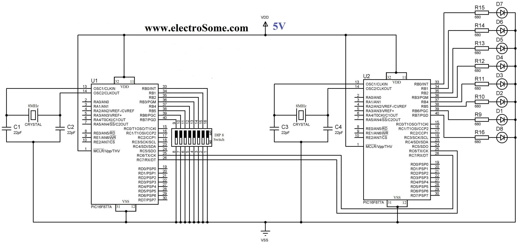
Note 1 : TX of Master Microcontroller is connected to RX of Slave Microcontroller and RX of Master Microcontroller is connected to the TX of Slave Microcontroller.
Note 2 : Instead of using PULL UP or PULL DOWN resistors along with switch, we are using INTERNAL PULL UP of PORTB which is enabled in the program.
MPLAB XC8 Codes
Master Code
#define _XTAL_FREQ 8000000
#include <xc.h>
#include <pic16f877a.h>
#include "uart.h"

// BEGIN CONFIG
#pragma config FOSC = HS
#pragma config WDTE = OFF
#pragma config PWRTE = OFF
#pragma config BOREN = ON
#pragma config LVP = OFF
#pragma config CPD = OFF
#pragma config WRT = OFF
#pragma config CP = OFF
//END CONFIG

void main()
{
  TRISB = 0xFF; //PORTB as Input
  nRBPU = 0;    //Enables PORTB Internal Pull Up Resistors
  UART_Init(9600);

  do
  {
    UART_Write(PORTB);
    __delay_ms(100);
  }while(1);
}
Slave Code
#define _XTAL_FREQ 8000000
#include <xc.h>
#include <pic16f877a.h>
#include "uart.h"
// BEGIN CONFIG
#pragma config FOSC = HS
#pragma config WDTE = OFF
#pragma config PWRTE = OFF
#pragma config BOREN = ON
#pragma config LVP = OFF
#pragma config CPD = OFF
#pragma config WRT = OFF
#pragma config CP = OFF
//END CONFIG

void main()
{
  TRISB = 0x00; //PORTB as Output
  UART_Init(9600);

  do
  {
    if(UART_Data_Ready())
       PORTB = UART_Read();
    __delay_ms(100);
  }while(1);
}
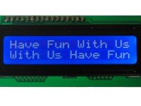
Want to See the Output ?
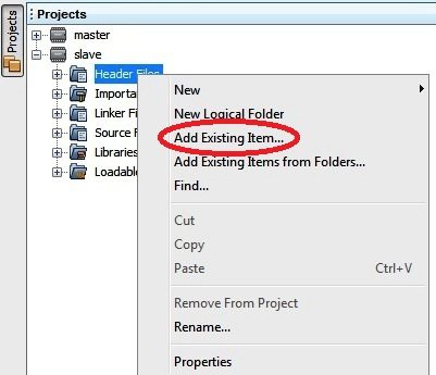
Note : Don’t forget to copy the header file ‘uart.h’ to your project folder and add it to project tree when you create a new project.
Download
You can download entire project files here…


You can download it from the above link.
Hi. Where may I found the file uart.h?
Sorry, I don’t have ready example code now.
A simple solution would be as below.
Consider the size of the float variable is 4 bytes..
you can copy it to a 4 byte character array using memcpy().
Then you can send it easily send it via UART..
In the receiver side you can do the same memcpy() to copy back to float variable from the array.
If you are looking for a professional support you can mail [email protected].
can u please share an example code??
I had figured that an RS232 to USB converter would be the easiest way. I have been trying to use a PIC that had an internal USB (PIC18F4550) but I haven’t been able to get it to work. I just ordered a serial to USB converter to give it a test. My development board has the RS232 port. I may need help with the code. When I do I will send my request to ligo. Thank you very much. Chris.
If you are planning to use a serial port (UART) of a PIC microcontroller.. you would need a USB to UART converter in the middle..
Thank you for the reply. The machine with the USB port is designed to be controlled by and hooked directly to a PC. I want to not use the PC any longer. I want to control the machine from a PIC. My question was asking if I needed any kind of signal level conversion or will the TTL from the PIC be able to directly connect to the machines USB Port?
I don’t understand the term “USB port to receive ASCII commands”. If your machine accepts TTL serial communication (9600 8N1), you can use the UART, just need to program the microcontroller appropriately. If you are looking for professional support you can mail [email protected].
Hi,
I want to control a machine that has a USB port to receive ASCII commands. I need to control it from a PIC with no PC. Can I just feed the TTL into the machines USB port? If not, is there a way to convert the signals from the PIC to something the machine can understand? It is a simple machine that is looking for 9600 8N1. Thank you.
thank you, it’s very helpful to me
Nice Tutorial Sir
Yes I got the Solution..!!
unsigned int Data=1234;
unsigned char Byte[4];
Byte[0]=data%1000+’0′; //Making it ASCII character
Byte[1]=data%1000/100+’0′;
Byte[2]=data%1000%100/10+’0′;
Byte[3]=data%1000%100%10+’0′;
I want to send 16bit integer data from Microcontroller USART to PC….How should I send it?….Because TXREG is only 8 bits…Please Help
Great!
Thanks for the feedback.
You are welcome to share your project here. Mail us at [email protected]
Great tutorial! thank you.
Thank you so much!
It works very well in my PIC16F883+HC-06 bluetooth module with android app.
Are you using 16F877A and above codes ??
Make sure that your UART is initialized.
Just write a loop and use the function UART_Read().
Hi there I have an issue. My code never leaves the while(!TRMT); condition in the UART_Write(char data) function, or better it runs once but then it waits there forever. What can be wrong? Thanks in advance.
Hi, I have a problem.
How I can read a text string, for example read a ” Hello”?
char data;
unsigned int num=4;
unsigned char text[3];
text =UART_Read_Text (data,num); // wrong
I do not know how to write the code
Sorry, we cannot provide programs as per the requirements of each and everyone visiting our website. You should try to develop it yourself based on the above tutorial.
You can also hire one of our engineers if you need support like that.
I have PIC16F877A microcontroller, i am sending data from UART to PIC18F67K22 , i want to send with the help of two different chip. I failed to do this. Kindly send me program.
You can use the same code in any pic microcontrollers… but you might need to make minor changes depending on the microcontrollers. Please check the device specific datasheet for more information.
First you should compare the difference of modules of both pic microcontrollers by checking the datasheet. Then you might need to make some minor changes to make it function.
sir please UART use PIC16f877a but receive another chip
Hi, Ligo George,
Thanks a lot for the useful examples!
Can you tell me how to modify this code to make it work with PIC18F2550? The only difference that I found is the Send Break bit (bit 3 from the TXSTA register).
Thanks in advance! 🙂
You cannot compare string like that. You have 2 options.
1. Compare each character in the array. OR
2. Use strcmp(), don’t forget to include string.h
hi, thanks for your code.
i would like to ask how could i receive text from the serial data and manipulate it?
example:
If (received text = “hello”)
{
do something
}
It is very simple, you need to just enable the interrupt by writing to corresponding registers. Then the interrupt function will be automatically called.
sorry pic16f877a
How to use serial interrupt in pic15=6f877a…plz can u post related to that.?
Sorry, I don’t have assembly codes.
Would it be possible to see your full assembly code? (opposed to just the main loop). Thanks in advance 🙂
Quick question, using a PIC18F14K50 I just want to echo what I type into the terminal.
eg Terminal “inforn”
pic echo “info”
so far i can send information through UART but I cannot seem to get the right structure to receive and act upon the received information. I’m new to pics and am transitioning from Atmels to PIC’s I do know C and C++ but its a bit rusty any help would be great.
so far this is what i have now in main. I have tried a few other structures but cant seem to get the pic to echo back what i type into the terminal.
TRISBbits.RB6 = 0; //PORTB RB6 OUTPUT
TRISBbits.RB7 = 1; //PORTB RB7 INPUT
//nRBPU = 0; //enables PortB internal pull ups
UART_Init(9600);
while(1)
{
//UART_Write_Text(“Hello There PIC18F14K50!rn”);
wait_ms(500);
if(UART_Data_Ready())
{
if(UART_Read() == ‘a’ + ‘n’ + ‘r’)
{
UART_Write(“Hellorn”);
}
}
}
Thanks by the way.
I hope that you can use it. Use the lowest baud rate as far as possible.
The above tutorial is for PIC 16F877A, you might need to make some changes to work with PIC 18F14K22.
Please read the device specific datasheet for that.
hi Can I use this code to interface stx882 and srx882
Please help with my question.
I have to build a wireless transmission using pic18lf14k22
Size of float is 4byte.. You can send 1 byte through uart at a time. So you can send 4 bytes sequentially. You may also add a start byte and stop byte to indicate start and stop.
Hi, I’m trying to send a value got from de adc of the PIC, is it possible to send a float over the uart, if it so can you tell me how to do it? I’ve tried doing this:
#define _XTAL_FREQ 5000000
#define RS RD2
#define EN RD3
#define D4 RD4
#define D5 RD5
#define D6 RD6
#define D7 RD7
#include ;
#include “lcd.h”;
#include;
#include “uart.h”
// BEGIN CONFIG
#pragma config FOSC = XT // Oscillator Selection bits (HS oscillator)
#pragma config WDTE = OFF // Watchdog Timer Enable bit (WDT disabled)
#pragma config PWRTE = OFF // Power-up Timer Enable bit (PWRT disabled)
#pragma config BOREN = ON // Brown-out Reset Enable bit (BOR enabled)
#pragma config LVP = OFF // Low-Voltage (Single-Supply) In-Circuit Serial Programming Enable bit (RB3 is digital I/O, HV on MCLR must be used for programming)
#pragma config CPD = OFF // Data EEPROM Memory Code Protection bit (Data EEPROM code protection off)
#pragma config WRT = OFF // Flash Program Memory Write Enable bits (Write protection off; all program memory may be written to by EECON control)
#pragma config CP = OFF // Flash Program Memory Code Protection bit (Code protection off)
void main()
{
unsigned int u;
float f;
float v;
char s[20];
char q[20];
char t[64];
int a;
int b=0;
ADCON0bits.ADCS = 0; //Selecting the clk division factor = FOSC/2
ADCON1bits.ADCS2 = 0; //Selecting the clk division factor = FOSC/
ADCON1bits.ADFM = 1; //Result right justified
ADCON1bits.PCFG = 0; //Setting all the analog ports as Analog inputs
ADCON0bits.ADON = 1; //Turns on ADC module
ADCON0bits.CHS = 0; //Selects channel 0 ( AN0 )
TRISD = 0x00;
Lcd_Init();
UART_Init(9600);
while(1)
{
ADCON0bits.GO = 1;
while (ADCON0bits.nDONE) continue; //wait till ADC conversion is over
f = (ADRESH<<8) + ADRESL ; //Merging the MSB and LSB
v=f*5/1023;
sprintf(s, "VALOR = %2.2g", v);
Lcd_Set_Cursor(1,1);
Lcd_Write_String(s);
sprintf(q, "Integer = %f", f);
Lcd_Set_Cursor(2,1);
Lcd_Write_String(q);
__delay_ms(50);
nRBPU=0; //enables portb internal pull up resistors
UART_Write_Text(" value = ");
sprintf(t, "%f",v);
UART_Write(t);
__delay_ms(1000);
}
}
HOPE YOU CAN HELP ME
You can use simply, UART_Write_Text(“HELLO”);
Hi, Can you please give me an example of how to use the functions to send a string, I am trying at the moment and the slave does not seem to be receiving anything, however it works with your example with port B. Thanks in advance
I tried this code to send a matrix between 2 PIC18, and worked. Thanks so much.
Leo Módulos – From Brazil
You can simply use above functions to send AT commands .. and to read responses for GSM modem.
Can you guide me to interface PIC16F877a with GSM (i have TTL outputs) using MPLABX anc xc8??
Use like this :
if(UART_Data_Ready())
{
}
i need to make a “if” when is receiving something if not the program shall continue.
how i could do that?
this exemple will work?
if (!TRMT){// the data is ready
//do something
}
//if not ready continue with the program
Sorry for my english
thanks for your help
Above code is 100% working and it is tested in hardware..
1. Set baud-rate correctly..
2. Use No parity..
3. 8 bit data
4. Single Stop bit..
I hope that you can use above functions without any change..
Hi Ligo george ,
I am trying to send string of data from controller to PC via VSPE , virtual serial port . i am not able to receive any data on the Hyper terminal .
i am using the baud rate 9600 .
could send me the working code for this .
Please help me how do i do this .
Hi Ligo george ,
I am trying to send string of data from controller to PC via VSPE , virtual serial port . i am not able to receive any data on the Hyper terminal .
i am using the baud rate .
Please help me how do i do this .
Hi ligo ,
can i get pls knw how to send a string from controller to a PC using virtual serial port VSPE.
thanks in advance
Yes, you can continuously read using UART_Read() function in a loop…. until a limiting character is reached.
can I read text its length is unknown ?