

Custom Characters on LCD using PIC – MPLAB XC8
Contents
I hope that you already go through our tutorial, Interfacing LCD with PIC Microcontroller – MPLAB XC8. HD44780 compatible controllers used in these LCDs allows us to define 8 custom characters in addition to the standard pre-programmed characters. In this tutorial we will learn, how to create custom characters on LCD using PIC Microcontroller and MPLAB XC8 compiler.
DDRAM, CGROM and CGRAM
CGROM – Character Generator ROM
This is the memory which holds 5×8 or 5×10 dot patterns of predefined characters in the LCD. It can generate 208 5×8 dot character patterns and 32 5×10 dot character patterns.
DDRAM – Display Data RAM
This is the memory which holds the character data which is currently displayed on the LCD screen. Its capacity is 80×8 bits, ie 80 characters.
CGRAM – Character Generator RAM
This memory works similar to CGROM but as this is a RAM we can modify its data any time. So we can store our custom character patterns in this memory through program. We can store up to eight 5×8 character dot patterns or four 5×10 character dot patterns in this memory.
Character Generation
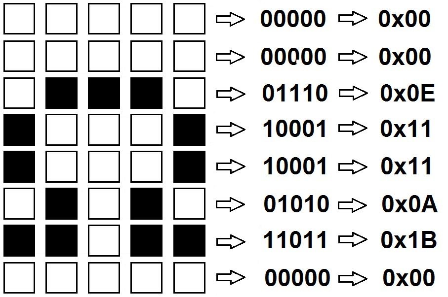
Characters are displayed on the LCD using 5×8 or 5×10 dot matrix. Most of the commonly available displays uses 5×8 dot matrix. We can simply create a custom character by defining each pixel in the dot matrix. Here is an example of creating Ω symbol on 5×8 dot matrix.
MPLAB XC8 Code
Note that the following program uses our MPLAB XC8 LCD Library and you should include the header file “lcd.h” to your project directory.
#define _XTAL_FREQ 8000000

#define RS RD2
#define EN RD3
#define D4 RD4
#define D5 RD5
#define D6 RD6
#define D7 RD7

#include <xc.h>
#include <stdio.h>
#include "lcd.h";

// BEGIN CONFIG
#pragma config FOSC = HS   // Oscillator Selection bits (HS oscillator)
#pragma config WDTE = OFF  // Watchdog Timer Enable bit (WDT enabled)
#pragma config PWRTE = OFF // Power-up Timer Enable bit (PWRT disabled)
#pragma config BOREN = ON  // Brown-out Reset Enable bit (BOR enabled)
#pragma config LVP = OFF   // Low-Voltage (Single-Supply) In-Circuit Serial Programming Enable bit (RB3 is digital I/O, HV on MCLR must be used for programming)
#pragma config CPD = OFF   // Data EEPROM Memory Code Protection bit (Data EEPROM code protection off)
#pragma config WRT = OFF   // Flash Program Memory Write Enable bits (Write protection off; all program memory may be written to by EECON control)
#pragma config CP = OFF    // Flash Program Memory Code Protection bit (Code protection off)
//END CONFIG

const unsigned short MyChar5x8[] = {
  0x00, 0x00, 0x0A, 0x1F, 0x1F, 0x0E, 0x04, 0x00, // Code for char num #0
  0x0E, 0x1B, 0x11, 0x11, 0x11, 0x11, 0x1F, 0x00, // Code for char num #1
  0x0E, 0x1B, 0x11, 0x11, 0x11, 0x1F, 0x1F, 0x00, // Code for char num #2
  0x0E, 0x1B, 0x11, 0x11, 0x1F, 0x1F, 0x1F, 0x00, // Code for char num #3
  0x0E, 0x1B, 0x11, 0x1F, 0x1F, 0x1F, 0x1F, 0x00, // Code for char num #4
  0x0E, 0x1F, 0x1F, 0x1F, 0x1F, 0x1F, 0x1F, 0x00, // Code for char num #5
  0x00, 0x04, 0x02, 0x1F, 0x02, 0x04, 0x00, 0x00, // Code for char num #6
  0x00, 0x00, 0x0E, 0x11, 0x11, 0x0A, 0x1B, 0x00  // Code for char num #7
};
void InitCustomChars()
{
  char i;
  Lcd_Cmd(0x04);   // Set CGRAM Address
  Lcd_Cmd(0x00);   // .. set CGRAM Address
  for (i = 0; i <= 63 ; i++)
    Lcd_Write_Char(MyChar5x8[i]);
  Lcd_Cmd(0);      // Return to Home
  Lcd_Cmd(2);      // .. return to Home
}

int main()
{
  TRISD = 0x00;        // PORTD as Output
  Lcd_Init();
  InitCustomChars();   // Write custom characters to LCD memory
  while(1)
  {
    Lcd_Clear();
    Lcd_Set_Cursor(1,1);
    Lcd_Write_Char(0); // Display Custom Character 0
    Lcd_Write_Char(1); // Display Custom Character 1
    Lcd_Write_Char(2); // Display Custom Character 2
    Lcd_Write_Char(3); // Display Custom Character 3
    Lcd_Write_Char(4); // Display Custom Character 4
    Lcd_Write_Char(5); // Display Custom Character 5
    Lcd_Write_Char(6); // Display Custom Character 6
    Lcd_Write_Char(7); // Display Custom Character 7
    __delay_ms(1000);
  }
  return 0;
}
Hope you can understand the working of the program from above comments. Please comment below if you have any doubts.
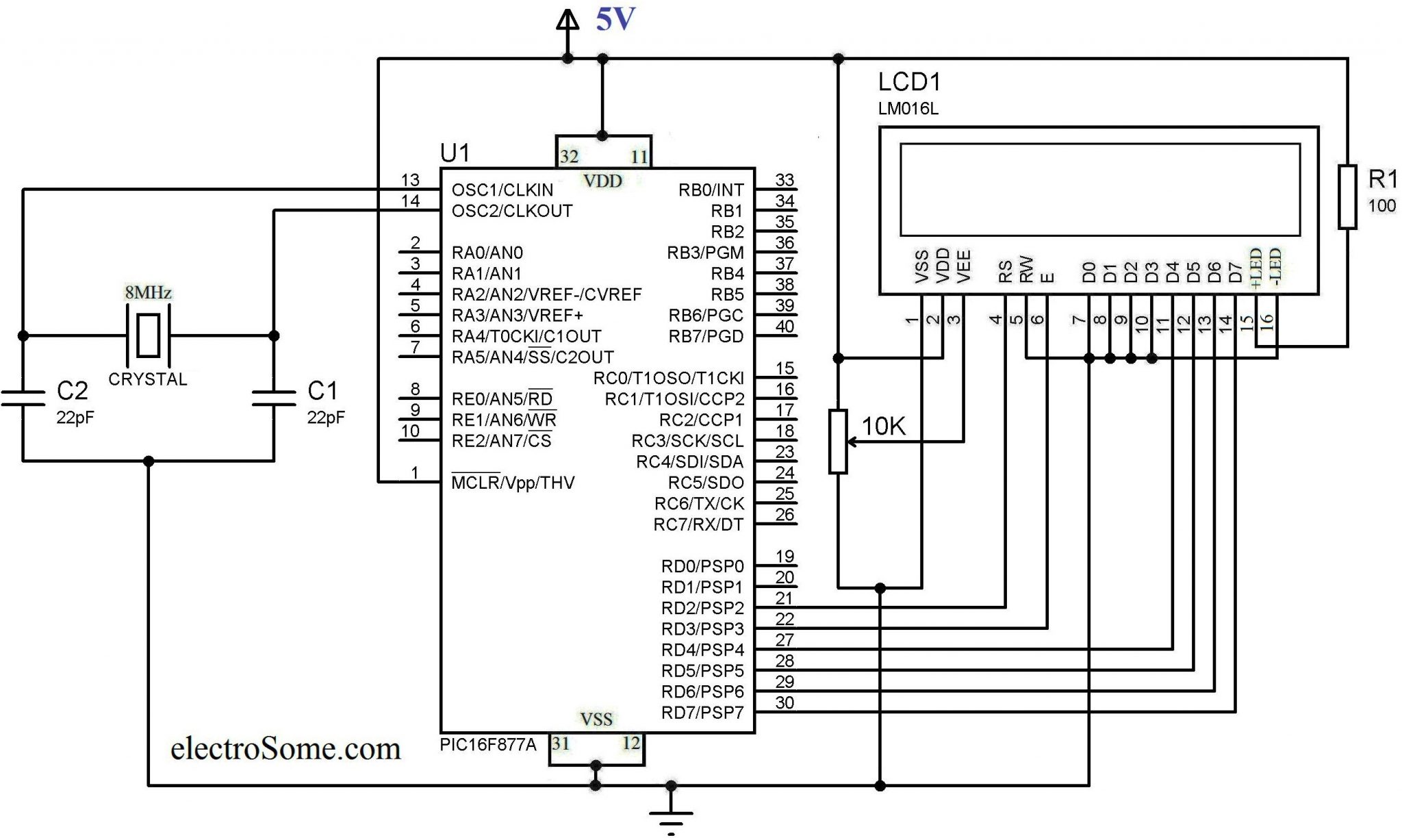
Circuit Diagram
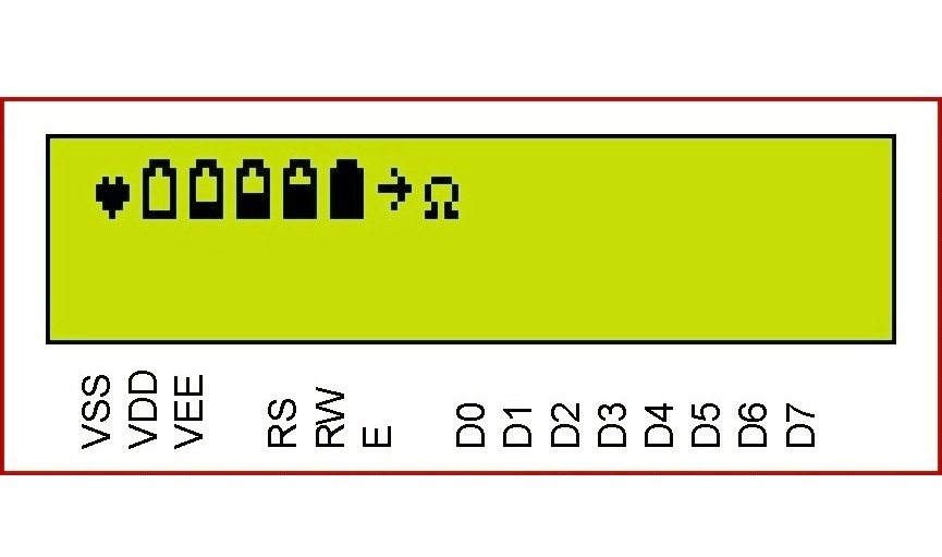
Output
Download Here


Hi Ligo, I really enjoy your projects and how you explain the workings of it !!!
I’m new to C programming and is still busy getting the grips of it. I used to program in assembly but knew
some or other time I will have to learn this language.Thank you once again for making the learning so easy.
Thanks
Jonathan
Hi, very good guide, may I ask for pure sine wave system guide please.
Thank you, you saved my life!
Hello,
Who told to use 49 ? 63 is the correct value.
Dear Ligo, i tried to display 8 custom characters using a 20 x 4 lcd but the 7th and 8th custom character didn’t appear the way they were supposed to , so i took another look at this tutorial and used ” i <= 63 " in the for loop like you used and it worked perfectly. Please could explain how the " i <=63 " affects the display.THANK YOU. PS i used " i <= 49" in the first code.
Please read the article : https://electrosome.com/lcd-pic-mplab-xc8/ and the datasheet of HD44780 controller used in the LCD.
Dear Ligo
Could you please explain more about function Lcd_cmd();.I don’t understand how to set adress CGRAM.
Why we set Lcd_cmd(0x04) and Lcd_cmd(0x00);.
Thank you