

Interfacing Servo Motor with Arduino Uno
Contents
In this tutorial we will learn how to interface servo motor with Arduino Uno. Servo Motor is an electrical linear or rotary actuator which enables precise control of linear or angular position, acceleration or velocity. Usually servo motor is a simple motor controlled by a servo mechanism, which consists of a positional sensor and a control circuit. Servo motor is commonly used in applications like robotics, testing automation, manufacturing automation, CNC machine etc. The main characteristics of servo motor are low speed, medium torque, and accurate position.
Components Required
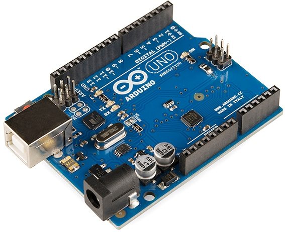
- Arduino Uno
- Servo Motor
- Jumper Wires
Hobby Servo Motor

Specifications
- Servo Motor consists of three pins: VCC, GROUND, and PWM signal pin.
- The VCC and GND is for providing power supply, the PWM input pin is used for controlling the position of the shaft by varying pulse width.
- Minimum Rotational Angle : 0 degrees
- Maximum Rotational Angle : 180 degrees
- Operating Voltage : +5V
- Torque : 2.5 kg/cm
- Operating Speed : 0.1 s/60 degree
- DC Supply Voltage : 4.8V to 6V
Working
The hobby servo motor which we use here consists of 4 different parts as below.
- Simple DC Motor
- Potentiometer
- Control Circuit Board
- Gear Assembly
Potentiometer is connected to output shaft of the servo motor helps to detect position. Based on the potentiometer value, the control circuit will rotate the motor to position the shaft to a certain angle. The position of the shaft can be controlled by varying the pulse width provided in the PWM input pin. Gear assembly is used to improve the torque of the motor by reducing speed.
Circuit Diagram

Description
- The VCC pin (Red Color) of the Servo Motor is connected to the 5V output of the Arduino Board.
- The GND pin (Brown Color) of the Servo Motor is connected to the GND pin of the Arduino Board.
- The PWM input pin (Yellow Color) of the Servo Motor is connected to the PWM output pin of the Arduino board.
Program
#include <Servo.h>

Servo servo;
int angle = 10;

void setup() {
    servo.attach(3);
    servo.write(angle);
}
void loop()
{
    // rotate from 0 to 180 degrees
    for(angle = 10; angle < 180; angle++)
    {
        servo.write(angle);
        delay(15);
    }
    // now rotate back from 180 to 0 degrees
    for(angle = 180; angle > 10; angle--)
    {
        servo.write(angle);
        delay(15);
    }
}
Code Explanation
- The position of the shaft is kept at 10 degrees by default and the Servo PWM input is connected to the 3rd pin of the Arduino Uno.
- In the first for loop, motor shaft is rotated from 10 degrees to 180 degrees step by step with a time delay of 15 milliseconds.
- Once it reaches 180 degree, it is programmed to rotate back to 10 degree step by step with a delay of 15 milliseconds in the second for loop.
Functioning
Wire the circuit properly as per the circuit diagram and upload the program. You can see that the servo motor is rotating as per the program. Please see the video below for more details.
Output
Conclusion
Hope you understood about the functioning of the servo motor with the help of Arduino programming. You can modify this code for your robotic applications and have fun. Please feel free to comment below if you have any doubts.


