

Using UART of PIC Microcontroller – Hi Tech C
Contents
UART stands for Universal Asynchronous Receiver / Transmitter. It is a serial communication interface which uses two lines for sending (TX) and receiving (RX) data. As its name indicates it is an asynchronous communication interface, which means it doesn’t need to send clock along with it as in synchronous communications. UART is the communication standard of our old computer’s RS-232 serial port. Most of the Microchip’s PIC Microcontrollers have built in USART Module. USART stands for Universal Synchronous Asynchronous Receiver Transmitter. It can be configured in the following Modes :
- UART – Asynchronous (Full Duplex)
- USRT Master – Synchronous (Half Duplex)
- USRT Slave – Synchronous (Half Duplex)
In this tutorial we are concentrating on sending and receiving data in the UART Mode using Hi-Tech C compiler. You may already know that Hi-Tech C has no built in functions for these, so we require some hardware knowledge for writing the code. I am going to explain it in deeply. If you don’t need deep knowledge in this, please skip to the coding section.
PIC 16F877A USART in Detail
USART Registers – PIC 16F877A
TXSTA – Transmit Status and Control Register
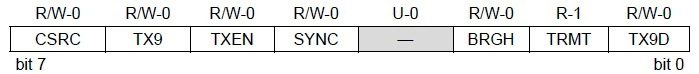
- Bit 7 CSRC : Clock Source Select Bit, this bit has no application in the Asynchronous mode operation of USART module. It is used to select master or slave mode in Synchronous mode operation.
- Bit 6 TX9 : When this bit is set it enables the 9 bit transmission otherwise 8 bit transmission is used. 9th bit in the 9 bit transmission mode is commonly used as parity bit.
- Bit 5 TXEN : Setting this bit enables the transmission. In the synchronous mode operation CREN and SREN bits of RCSTA register overrides this bit.
- Bit 4 SYNC : This is the USART Mode select bit. Setting this bit selects Synchronous mode while clearing this bit selects Asynchronous mode.
- Bit 3 Unimplemented : This bit is unimplemented and will read as 0.
- Bit 2 BRGH : This is the High Baud Rate Select bit for Asynchronous mode operation and is unused in Synchronous mode. Setting this bit selects High Speed and clearing this bit selects Low Speed baud rates. You will can see the baud rate calculation later in this article.
- Bit 1 TRMT : This is the Transmit Shift Register (TSR) status bit. This can be used to check whether the data written to transmit register is transmitted or not. When the TRS is empty this bit is set and when the TSR is full this bit will be 0.
- Bit 0 TX9D : This is the 9th bit of data in the 9 bit transmission mode. This is commonly used as parity bit.
RCSTA – Receive Status and Control Register

- Bit 7 SPEN : Serial Port Enable bit. Setting this bit enables serial port and configures RC7, RC6 as serial port pins.
- Bit 6 RX9 : Setting this bit enables 9 bit reception otherwise it will be in 8 bit reception mode.
- Bit 5 SREN : Single Receive Enable bit. This bit has no effect on Asynchronous mode and Synchronous Slave mode. Setting this bit will enables Single Receive. This bit will cleared after the reception is complete.
- Bit 4 CREN : Continuous Receive Enable bit. Setting this bit will enable Continuous Receive. In the Synchronous Mode CREN overrides SREN.
- Bit 3 ADDEN : Address Detect Enable bit. This bit is applicable only in Asynchronous 9 bit mode. Setting this bit enables Address Detect.
- Bit 2 FERR : Framing Error bit. 1 at this bit stands for Framing Error while 0 stands for No Framing Error.
- Bit 1 OERR : Overrun Error bit. A high at this bit indicates that Overrun error has occured.
- Bit 0 RX9D : This is the 9th bit of Received Data and is commonly used as Parity Bit.
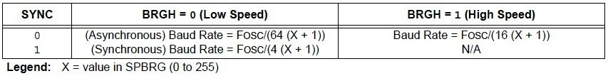
USART Baud Rate Generator (BRG)
Baud Rate Generator provides the required clock for the data transmission and reception. USART module has a dedicated 8 bit baud rate generator which supports both Synchronous and Asynchronous modes. The 8-bit SPBRG register controls the time period of this free running timer. In Asynchronous mode BRGH, 2nd bit of TXSTA register also controls the generated baud rate but in Synchronous mode it is ignored. Baud Rate can be calculated from the following equations, where FOSC is the clock frequency of the microcontroller.
Hi-Tech C Programming
Initializing UART
char UART_Init(const long int baudrate)
{
  unsigned int x;
  x = (_XTAL_FREQ - baudrate*64)/(baudrate*64); //SPBRG for Low Baud Rate
  if(x>255) //If High Baud Rate required
  {
    x = (_XTAL_FREQ - baudrate*16)/(baudrate*16); //SPBRG for High Baud Rate
    BRGH = 1; //Setting High Baud Rate
  }
  if(x<256)
  {
    SPBRG = x; //Writing SPBRG register
    SYNC = 0; //Selecting Asynchronous Mode
    SPEN = 1; //Enables Serial Port
    TRISC7 = 1;
    TRISC6 = 1;
    CREN = 1; //Enables Continuous Reception
    TXEN = 1; //Enables Transmission
    return 1;
  }
  return 0;
}
Note : 6th and 7th bit of TRISC registers are set as prescribed in the datasheet.
Transmitting Data through UART
Writing a Character
void UART_Write(char data)
{
  while(!TRMT); //Waiting for Previous Data to Transmit completly
  TXREG = data; //Writing data to Transmit Register, Starts transmission
}
Checking Transmit Register
This functions returns 1 if the transmit register is Empty otherwise return 0. It can be used to check whether the written data is completed transmission.
char UART_TX_Empty()
{
  return TRMT; //Returns Transmit Shift Status bit
}
Writing Text
The following function can be used to write a string or array of characters to UART. It is accomplished by continuous use of character writing function UART_Write().
void UART_Write_Text(char *text)
{
  int i;
  for(i=0;text[i]!='\\0';i++)
    UART_Write(text[i]);
}
Receiving Data Through UART
Data Received or Not
The following function can be used to check whether the data is ready to read from the Receive Register. It uses the flag bit RCIF which will be set when the data reception is completed.
char UART_Data_Ready()
{
  return RCIF;
}
Reading a Character
The following function wait till the reception is complete and reads 8 bit data from the Receive Register.
char UART_Read()
{
  while(!RCIF); //Waits for Reception to complete
  return RCREG; //Returns the 8 bit data
}
Reading Text
The following function can be used to read a desired length of text or sequence of characters continuously.
void UART_Read_Text(char *Output, unsigned int length)
{
  int i;
  for(int i=0;i<length;i++)
    Output[i] = UART_Read();
}
For simplifying the program readability we put all the above function to a header file ‘uart.h’. Thus you just need to include this header file and use required functions. For demonstrating the working of these functions we are using the following example.
PIC to PIC Communication using UART
In this example we are controlling LED’s connected to a PIC using Switch’s connected to another PIC Microcontroller. For the sake of explanation call these microcontrollers Slave and Master respectively. In the circuit diagram given below a DIP 8 Switch is connected to PORTB of the Master Microcontroller which is configured as Input Port. Pull Up resistors (10KΩ) are connected to this port to make each pin HIGH when the switch is OFF. When a Switch is turned ON, the corresponding pin will be Grounded (LOW).
Data Read from the PORTB of Master Microcontroller is send to Slave Microcontroller using UART interface. The Slave Microcontroller writes the received data to its PORTB which is configured as Output. Thus LED’s connected to Slave Microcontroller will Glow depending upon the status of the DIP Switch connected to the Master Microcontroller.
Circuit Diagram
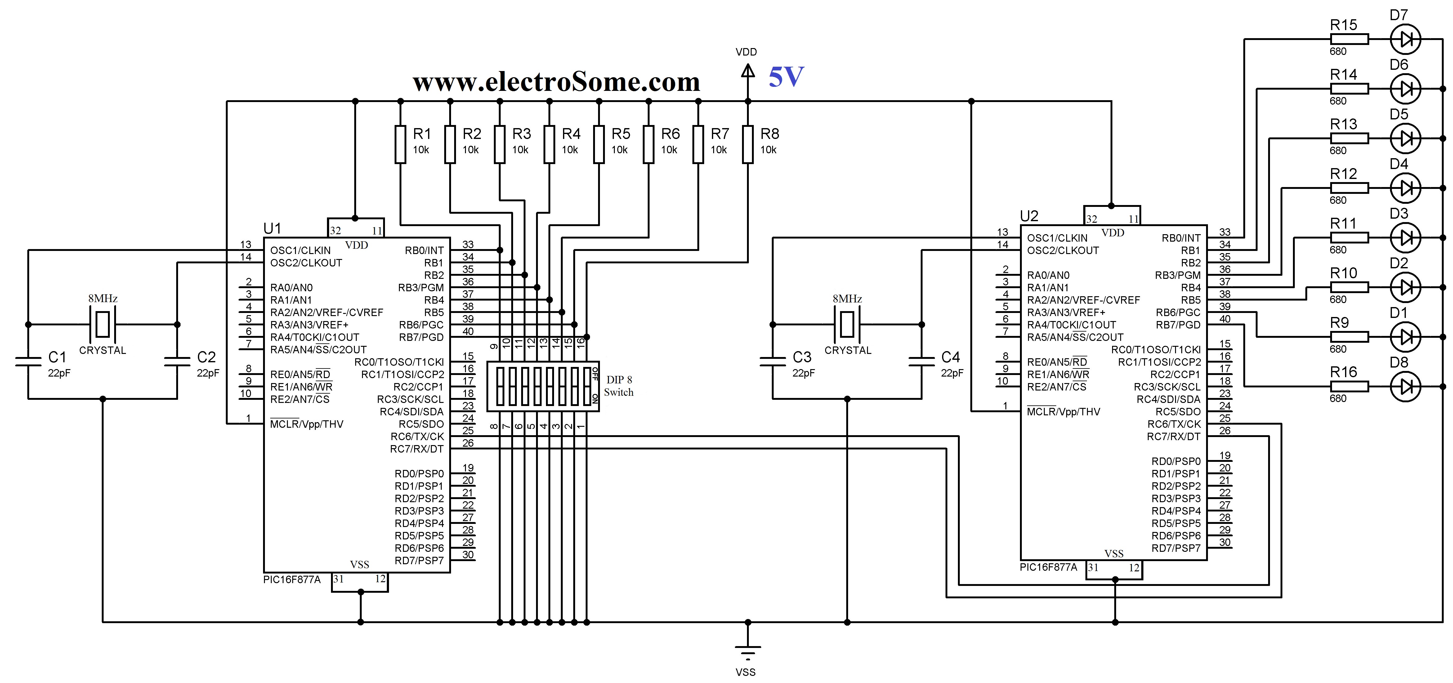
Note : TX of Master Microcontroller is connected to RX of Slave Microcontroller and RX of Master Microcontroller is connected to the TX of Slave Microcontroller.
Hi-Tech C Codes
Master Code
#include<htc.h>

#define _XTAL_FREQ 8000000
#include "uart.h"

void main()
{
  TRISB = 0xFF; //PORTB as Input
  UART_Init(9600);

  do
  {
    UART_Write(PORTB);
    __delay_ms(100);
  }while(1);
}
Slave Code
#include<htc.h>
#define _XTAL_FREQ 8000000 //Clock Frequency
#include "uart.h"

void main()
{
   TRISB = 0x00; //PORTB as Output
   UART_Init(9600);

   do
   {
      if(UART_Data_Ready())
        PORTB = UART_Read();
     __delay_ms(100);

   }while(1);
}
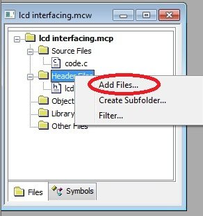
Note : Don’t forget to add Header file to the Project Folder and File list before compiling.
Download Here
You can download ‘uart.h’ header file, Hi-Tech C and Proteus files here…


sir ,
i took ur code as reference and wrote the following code,but whenever i read a string ,the following code isint working,can u help me with this
#include
#include
#include
#define _XTAL_FREQ 4000000
__CONFIG(FOSC_HS & WDTE_OFF & PWRTE_OFF & BOREN_ON & LVP_OFF);
/******************************BASIC CONFIGURATION SETTINGS********************/
void UART_Init()
{
TXSTA = 0x24;
RCSTA = 0x90;
SPBRG = 25;
TRISC=0x80;
}
/*************************TO WRITE A CHAR TO SERIAL PORT*****************************/
void UART_Write(char data)
{
TXREG = data; //Writing data to Transmit Register, Starts transmission
while(!TXIF); // stay until TXIF remains 0, if TXIF =1 indicates successfully transmitted previous bit ready to transmit next
TXIF = 0; //Waiting for Previous Data to Transmit completly
}
/***************To Write a string to serial*******************************/
void UART_Write_Text(char *text)
{
int i;
for(i=0;text[i]!=”;i++)
{
UART_Write(text[i]);
}
UART_Write(‘~’);
}
/*****************************to read a char from serial**************************/
char UART_Read()
{
while(!RCIF); //Waits for Reception to complete
return RCREG; //Returns the 8 bit data
}
/*******************************to read a string to serial**********************************/
void ReadString(char *outstring)
{
char data;
char dataout[30]={0};
int index = 0;
memset(outstring,0,20);
memset(dataout,0,20);
data=UART_Read();
while(data!= ‘~’)
{
dataout[index++] = data;
data=UART_Read();
}
dataout[index++]=’n’;
dataout[index]=”;
memcpy(outstring, dataout, index);
}
/*********************main function************************/
void main()
{
UART_Init(); //initiate uart
int i=0;
char b[10]=”arvind~”;
char a[10];
while(1)
{
UART_Write_Text(b);
ReadString(a);
//__delay_ms(100);
//UART_Write_Text(a);
}
}
Above program is with Hi-Tech C. Kindly use the following link for MikroC
https://electrosome.com/pic-to-pic-communication-uart/
I have a same problem, I nedd receive a text.
Sorry, I don’t understand your question.
Hi, in the UART_Write function how can you check for the break character ‘\0’ when it is larger than one byte? I’m confused. Thx for your help.
hi
You can use the same configuration bits that used in the first tutorial, https://electrosome.com/blinking-led-pic-microcontroller-hi-tech-c/
what are the configuration bits for serial communication if i used port b as
You can use the same code of MPLAB XC8.. just change the header file xc.h to htc.h.
https://electrosome.com/em-18-rfid-module-pic/
hai….
i ned project program for Hi Tech c
title is show rfid code in lcd 2*16 display… pic16f877a
hai….
i ned project program for Hi Tech c
title is show rfid code in lcd 2*16 display…
Please use our forums (https://electrosome.com/forums) for asking doubts not related to above topic.
Don’t forget to mention details of your motor.
can any one tell me how to interface an encoder motor with uart using pic in mikro c?
Hope your problem is solved…
Please make your comments short as possible in future… It is very difficult and time consuming to read and understand long comments…
Solved, setting the value of register RCREG to 0x00.
Functional code:
void UART_Read_Flush() { RCREG = 0x00; }
chr = UART_Read();
if (chr >= 0x30 && chr <= 0x39) { in = 0; }
if (!in)
{
UART_Write(chr);
UART_Read_Flush();
in = 1;
}
Again this won’t stop transfer of the last RX:
chr = UART_Read();
if (chr >= 0x30 && chr <= 0x39) { in = 0; }
if (!in)
{
UART_Write(chr);
chr = '';
in = 1;
}
Hy, I use only one PIC, Proteus ISIS v8 for simulation and mikroC v5 to compile C programs into binary form to burn the chip. I came with a question about implementation logic of an UART echo mode ON. I came with two memory chunks CMain[n], and Buffer[n], if the Buffer[n] is empty UART_Read_Text(char*, unsigned char) will fill up the Buffer[n] zone then will coppy the Buffer[n] to the CMain[n] zone. If CMain[n] is not empty (then we know array contain something, and can write input to output. RX -> TX). After writing out to TX we need to clear memory zone, and I found setting first element to 0, of each two zones.
The problem on this logic is: TX will still bind to the last data of RX, in a forever loop.
My question is if we can write Buffer[n] without a forever TX of the last RX byte.
[CODE]
char cmain[50] = {0};
char buffer[20] = {0};
UART_Init(9600);
do
{
if(buffer[0] == 0)
{
UART_Read_Text(buffer, 20);
strcpy(cmain, buffer);
}
else if (cmain[0] != 0)
{
UART_Write_Text(cmain);
buffer[0] = 0;
cmain[0] = 0;
}
Delay_ms(100);
}
while(1);
[ENDCODE]
Thank, you KPSOFT
The above program is build for PIC 16F877A not for 16F877..
I am using pic16f887 and not able to receive the data which I am transmitting from ma computer terminal …plz help me with this
Sure, I will post it. Thanks for the suggestion.
pl post Tutorial for HC-05 Bluetooth Module using UART codes !
You can do it in different ways. For eg; you may convert that number to string and send it via UART.
Hello,
If we want to send, for example,15 numbers of 12 digits,how we should change the above UART codes to do that?
To use parity bits, you can edit the UART_Init function.. add TX9 = 1 to that function.
You can easily read multi-byte signals using above functions..
I hope that you can use it without any change in the code.
Great tutorial as always. But could you please make an example of UART where it uses parity bits? I know now (with the help of this post) how to do basic UART, but i still find it difficult to read a multi-byte signal. Thanks already
It was an html error while updating the website. It is corrected now. Thank you.
void UART_Write_Text(char *text)
{
int i;
for(i=0;text[i]!=”;i++)
UART_Write(text[i]);
}
There was no error in the header file in the download zip file.
Sorry to tell u that there is an error in a header file showing me error
void UART_Write_Text(char *text)
{
int i;
for(i=0;text[i]!=”;i++)
UART_Write(text[i]);
}
Sorry, above article deals with UART Asynchronous communication..
I can receive data on USART slave synchronous, but ican’t in master, Can you show me how to receiving data on USART master synchronous.
It will depend up on the programming language you are using..
SIR,
i wanna connect my pic to pc using serial port
i have a serial pin with max232 ready but still it would be better i am shown a shematic.
and also i wanna know how to send codes from computer
Thank you
The E stands for Enhanced Usart, its basically the same but with some extra features like Sleep/ Wake up on receive.
Sir,
I am using PIC 16F687 and trying to serially communicate between these two PIC’s.
the data sheet says EUSART can beimplemented, what is the main difference between UART and EUSART.
It would be kind if you would help me with the code to do the above job.
wow, tanx alot for your fast reply 🙂
The download link is updated..
Thanks..
hi mate the link to download the file is not working, can you update it please?
how can we send a text like “hi” from one pic and receive it on another pic.
i m using pic 16f887. wanna send text and also receive it. compiler mikroc
Thanks for sharing! Can I use this UART routines in MikroC with PIC16F628A?
BRGH16??
what is the relation between BRGH and BRGH16 bits ?
It is declared in the header file…..
Should not be zero one of those?
TRISC7 = 1;
TRISC6 = 1;
just as i thought. thanks for the reply 🙂
The two microcontrollers must have common ground.. otherwise it will not work..
Good day sir!
just want to confirm if the transmission will still occur even if the 2 microcontrollers do not have a common ground.
Thanks.