

Using Push Button Switch with Atmega32 and Atmel Studio
Contents

This tutorial is meant for beginners in the field of Atmel AVR programming. I hope that you already read my first tutorial Blinking LED using Atmega32 and Atmel Studio. In most of the embedded electronic projects you may want to use a push button switch to give user inputs to the microcontroller. To use a push button switch with a microcontroller, first you should configure the corresponding pin as input. Then we can easily read the status of that input pin and make required decisions. There are two types of push button switches Push To On and Push To Off, here we are using Push To On switch. In this tutorial a press at the switch turns ON the LED for 3 seconds.
Circuit Diagram
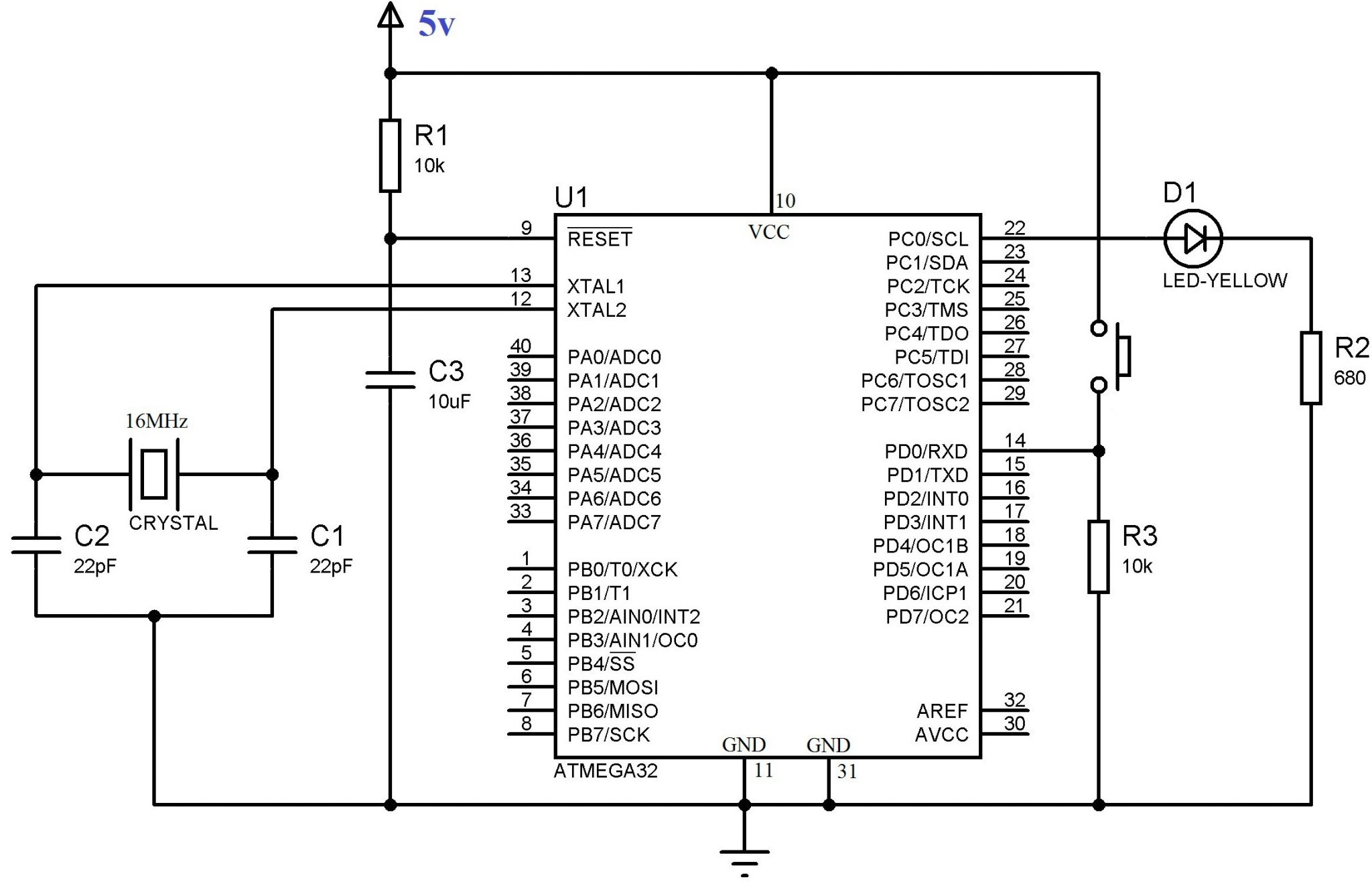
As described in the first tutorial 16 MHz crystal is used to provide clock to the Atmega32 microcontroller. 10µF capacitor and 10KΩ resistor is used to provide Power On Reset (POR) during the startup of microcontroller. LED is connected to the first pin of PORTC (PC0) of the microcontroller and a resistor is used to limit current through it. Push Button Switch is connected to the first pin of PORTD (PD0) of the microcontroller and a pull down resistor is provided to make the input LOW whenever the switch remain unpressed.
Program
#include <avr/io.h>
#include <util/delay.h>

int main(void)
{
  DDRC |= (1<<PC0); //Nakes first pin of PORTC as Output
  // OR DDRC = 0x01;
  DDRD &= ~(1<<PD0);//Makes firs pin of PORTD as Input
  // OR DDRD = 0x00; //Makes all pins of PORTD input
  while(1) //infinite loop
  {
    if(PIND & (1<<PD0) == 1) //If switch is pressed
    {
      PORTC |= (1<<PC0); //Turns ON LED
      _delay_ms(3000); //3 second delay
      PORTC &= ~(1<<PC0); //Turns OFF LED
    }
  }
}
As mentioned in the first tutorial DDR is the Data Direction Register which determines whether each pin is input or output, PORT register is the output register which is used to write output to pins and PIN register is the PORT Input Register which is used to read data from input pins. DDRC |= (1<<PC0) and PORTC |= (1<<PC0) sets (makes 1) the 0th bit of the specified registers. DDRD &= ~(1<<PD0) and PORTC &= ~(1<<PC0) resets (makes 0) the 0th bit of the specified registers. PIND & (1<<PD0) reads the 0th bit of the PORTD register. I hope that rest of the program is self explanatory and hence if you have any doubts please comment below.
Download Here
You can download Atmel Studio files and Proteus files here…


not bad 846861 &ab=aqzdrpgivu
Sir, please help,
3 Button indicate 3 person & it’s operate by a person .when the person press the button this time it’s indicate person 1 then button 2 indicate person no 2 & 3 for same.
i need this code which i want display it LCD .
When given the option to use “DDRC |= (1<<PC0)" or "DDRC = 0x01", why would anyone prefer the first over the latter? Especially for a beginner like myself the first one is… unreadable gibberish while the latter is marginally less so.
hello i want to interface 4 push buttons using interrupts with my atmega328p which has just 2 external interrupt !! how i can do it.
how should i modify the above code if i gave the input as a bend sensor and the led has to glow when the resistance of the bend sensor is between a range of values?
Sir, please help.
how to make 1 switch controlling 2 leds alternately.
When switch pressed at the firs time, led1 is on ( led2,off )…
then switch released, led1 off.
And when switch pressed again, led 2 on ( led1 off )
then switch released, led2 off.
Thank you very much.
Is it this the true way to acces push button for function push button…. https://uploads.disquscdn.com/images/53419738d9e6f8d7f2f9cacfd740bfc533c6b53f36c1b8ab4d523fac3d691758.png
https://uploads.disquscdn.com/images/7b231ac558bc4ee20933dd1aad7cb4f6d71fe837b7689f75b3dd4dc7c70e566f.png https://uploads.disquscdn.com/images/53419738d9e6f8d7f2f9cacfd740bfc533c6b53f36c1b8ab4d523fac3d691758.png
Hey everyone..how i want to make when i press the button,the led will toggle every 1s and when I press again it will change to 2 s(led blinking) and I press again it should be every 3 s,the led willl blink and then turn back to 1s…what I make in the code below,,it only turn on and off the led every time I push the button..
The code that our project prefer is interrupt..we dont want to used delay..can anyone help me
Did you rebuild the project properly after modifying the code ?
Sorry, you program code is not clear. Please edit and correct it.
This code won’t cause the LED to blink. You need to delay again after setting PC0 low.
You should lean yourself to program it. I am posting tutorials for teaching peoples like you, not to provide codes as per your requirement. It is a very simple task, so do it yourself.
int count=1;
if(button==0&&count==1)
{
led=1;
count++;
while(botton==0);
}
if(button==0&&count==2)
{
led=0;
count=1;
while(botton==0);
}
********//// try this code*****////
sir, i want to turn on and off led using the same push button i.e. when i press once it turns on and off when i press it again
It is very simple.. You can do it .. if you understand above program.
I want to turn on separate LED with a separate push button, plz guide me
…sorry ..i just don’t know why the code get compressed here 🙂
…let me again paste the code for correction in a readable manner….
My project is to detect positive dc volts ( 5v ) and consequently will light up LEDs sequentially with specific time intervals.
a) Specifically if the switch is pressed (positive volt signal), the IC should produce a 1-time sequential output of 8 LEDS (LED1 lights up. then after 2 seconds the LED1 turns-off. Then LED2 should turn-on for 1 minute, then turn-off. Then the LED3 should turn on for 2 seconds then turns-off. Then the same with LED4,5,6,7 and LED8 should turn-on for 1 minute then turns-off. During this period (from LED1 to LED8), the system must ignore any positive input. But after fully implementing the 8 outputs of the LED, only by this time it will again the system should implement another positive external signal.
b) The sequential output of IC must not be interrupted within that period (from LED1 to LED8 ) meaning it should lock itself. It should ignore any positve signal from any external input.
c) Only use Atmega32A-PU because this is the only available chip I have.
d) Please correct the C code if there’s any to correct.
e.) Please provide the correct HEX file also.
f.) Please note that this Atmega32A-PU will be programmed using Arduino by the electronic storekeeper.
g.) Please give instruction about the Fuses and bootloader if necessary as I have no ideas about this, and maybe the storekeeper might also have no idea, either.
h.) is crystal oscillator not needed in the circuit?
Here’s the C code: (please correct)
Attached are: circuit diagram & hex code (please correct)
*********************************************************************************/
#include
#include
#include
#define LED_PORT_DIR DDRC
#define LED_PORT PORTC
#define LED_DATA (0x01)
#define GLOW_LED(times) (LED_DATA << times)
#define DELAY_MS (2000) // in milli seconds
#define MAX_DELAY_MS (10000) // in milli seconds
#define LED_OFF (0x00)
/***** Function To Initialize Ports*****/
/* PORTC to output */
void init_ports()
{
LED_PORT_DIR = 0xFF;
}
/***** Function To Initialize Interrupts*****/
void init_interrupts()
{
cli(); //Disable Global Interrupts
GICR =(1<<INT0); //Set Bit6 of GICR to unmask INT0 interrupt.
MCUCR =(3<<ISC00); //Configuring MCUCR for Rising Edge interrupt for INT0
_delay_ms(MAX_DELAY_MS);
sei(); //Enable Global Interrupts
}
/***** Interrupt Service Routine For INT0*****/
ISR (INT0_vect)
{
static int i = 1; // to disable it for first time
if (!i) {
for (i = 0; i < 8; i++) {
LED_PORT = GLOW_LED(i);
if ((i+1) != 8) {
_delay_ms(DELAY_MS);
}
else{
_delay_ms(MAX_DELAY_MS);
}
}
}
i = 0;
LED_PORT = LED_OFF;
}
/***** Main Function *****/
int main(void)
{
init_ports();
_delay_ms(MAX_DELAY_MS);
init_interrupts();
while(1)
{
}
}
hi sir. can you please correct the code below as per the condition as follows: (i have already purchased Atmega32 twice but after setting up the circuit on the breadboard, there still no output.. please help me.
My project is to detect positive dc volts ( 5v ) and consequently will light up LEDs sequentially with specific time intervals. a) Specifically if the switch is pressed (positive volt signal), the IC should produce a 1-time sequential output of 8 LEDS (LED1 lights up. then after 2 seconds the LED1 turns-off. Then LED2 should turn-on for 1 minute, then turn-off. Then the LED3 should turn on for 2 seconds then turns-off. Then the same with LED4,5,6,7 and LED8 should turn-on for 1 minute then turns-off. During this period (from LED1 to LED8), the system must ignore any positive input. But after fully implementing the 8 outputs of the LED, only by this time it will again the system should implement another positive external signal.
b) The sequential output of IC must not be interrupted within that period (from LED1 to LED8 ) meaning it should lock itself. It should ignore any positve signal from any external input.
c) Only use Atmega32A-PU because this is the only available chip I have.
d) Please correct the C code if there’s any to correct.
e.) Please provide the correct HEX file also.
f.) Please note that this Atmega32A-PU will be programmed using Arduino by the electronic storekeeper.
g.) Please give instruction about the Fuses and bootloader if necessary as I have no ideas about this, and maybe the storekeeper might also have no idea, either.
h.) is crystal oscillator not needed in the circuit?
Here’s the C code: (please correct)
*********************************************************************************/
#include
#include
#include
#define LED_PORT_DIR DDRC
#define LED_PORT PORTC
#define LED_DATA (0x01)
#define GLOW_LED(times) (LED_DATA << times)
#define DELAY_MS (2000) // in milli seconds
#define MAX_DELAY_MS (10000) // in milli seconds
#define LED_OFF (0x00)
/***** Function To Initialize Ports*****/
/* PORTC to output */
void init_ports()
{
LED_PORT_DIR = 0xFF;
}
/***** Function To Initialize Interrupts*****/
void init_interrupts()
{
cli(); //Disable Global Interrupts
GICR =(1<<INT0); //Set Bit6 of GICR to unmask INT0 interrupt.
MCUCR =(3<<ISC00); //Configuring MCUCR for Rising Edge interrupt for INT0
_delay_ms(MAX_DELAY_MS);
sei(); //Enable Global Interrupts
}
/***** Interrupt Service Routine For INT0*****/
ISR (INT0_vect)
{
static int i = 1; // to disable it for first time
if (!i) {
for (i = 0; i < 8; i++) {
LED_PORT = GLOW_LED(i);
if ((i+1) != 8) {
_delay_ms(DELAY_MS);
}
else{
_delay_ms(MAX_DELAY_MS);
}
}
}
i = 0;
LED_PORT = LED_OFF;
}
/***** Main Function *****/
int main(void)
{
init_ports();
_delay_ms(MAX_DELAY_MS);
init_interrupts();
while(1)
{
}
}
Thanks in advance.
Dude use if(PIND & (1<<PD0)) instead of
if(PIND & (1<<PD0) == 1)
hello sir plz help me i ma using 7 switch auto off single -single swich plz sir code send me atmega8515
Sorry, I haven’t yet programmed AVR using Assembly Language..
Hi Mr Ligo George….how i want to convert this C programmed to AVR Assembly language….asm..
ok i will try that…thx a lot man..appreciate that…
Try this ::
#include
#include
int main(void)
{
DDRC = 0xFF; //Nakes PORTC as Output
while(1) //infinite loop
{
_delay_ms(300); // 300 mili seconds delay
PORTB = PORTB<= 0b10000000) //To reset to 00000001
{ //when the count becomes 10000000
_delay_ms(350); // 350 mili seconds delay
PORTB = 1;
}
}
i hope u can help me to write this programmed from beginning until ending. .i’m a new comer in AVR ATMega32….i want to create 8 LED running light project..
Thx a lot…
means PORT B ( 8 pin ) output must be connect to 8 LED right
for the starting programmed i’m still need to put this command right???
#include
#include
int main(void)
{
Try this :
do // To set infinite loop
{
_delay_ms(300); // 300 mili seconds delay
PORTB = PORTB<= 0b10000000) //To reset to 00000001
{ //when the count becomes 10000000
_delay_ms(350); // 350 mili seconds delay
PORTB = 1;
}
}while(1); // To set infinite loop
I hope that it ..will work..
Hi Mr Ligo…can u wrote to me full programmed for running light using 8 LED Push Button…thx..
Thx man…can i use the AVR Studio version 4.0 tu run this programmed?? i’m already install the AVR Studio version 4.0 before this….
Use
PORTC = 0xFF; //Turns ON All LEDs
_delay_ms(3000); //3 second delay
PORTC= 0x00; //Turns OFF All LEDs
instead of..
PORTC |= (1<<PC0); //Turns ON LED
_delay_ms(3000); //3 second delay
PORTC &= ~(1<<PC0); //Turns OFF LED
Hi, i want to use 8 LED blinking ( as a first tutorial ) using push button switch. So, the programming of AVR 32 should be modified right?? Which part of the programming should be adjust?? Can u guide me?? Thx…
thanks for the feedback..
Cool tutorial, thanks 🙂
You could also choose to connect the the button to PD2 (INT0), PD3 (INT1) or PB2 (INT2) so it can be configured to generate an external interrupt for more event-like functionality.