

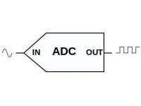
Analog to Digital Converter (ADC) in PIC Microcontroller
 ADC module of PIC microcontroller have usually 5 input for 28 pin devices and 8 inputs for 40 pin devices. The conversion of analog signal to PIC ADC module results in corresponding 10 bit digital number. PIC ADC module has software selectable high and low voltage reference input to some combination of VDD, VSS, RA2 and RA3.
In the following example project we will convert analog input to channel 1 to 10 bit digital number with low voltage reference (Vref-) 0v and high voltage reference (Vref+) 5V. The output will be displayed using 10 LEDs. You can change the Vref- and Vref+ by configuring the ADCON1 register.
ie,
0v = 0000000000
5v = 1111111111
Resolution = (Vref+ – Vref-)/(1024-1) (as it is 10 bit ADC)
= 5/1023
= 4.887 mV
Thus it means that for a change in 4.887mV, the binary output changes by 1.
Circuit Diagram

Note: VDD and VSS of the pic microcontroller is not shown in the circuit diagram. VDD should be connected to +5V and VSS to GND.
MikroC Program
unsigned int adc;
void main()
{
 ADCON1 = 0x80;
 TRISA = 0xFF; // PORTA is input
 TRISC = 0x3F; // Pins RC7, RC6 are outputs
 TRISB = 0;    // PORTB is output
 do
 {
 adc = ADC_Read(1); // Get 10-bit results of AD conversion
 //of channel 1
 PORTB = adc;      // Send lower 8 bits to PORTB
 PORTC = adc >> 2; // Send 2 most significant                  //bits to RC7, RC6
 } while(1);
}
You can vary the analog input value by varying the resistance of the potentiometer in the circuit.
This tutorial covers only the basic ADC operation. If you want to know more about it, please refer the datasheet of PIC 16F877A. If you have any doubt regarding this please do comment.


Hello Mr George.Thanks for this information. please i am trying to program pic16f886 adc to read 6 sensors from port a.From the datasheet, i read that the GO_Done bit should not be in the same instruction in ADCON0. Please i need your help to configure ADCON0. Or will it automatically configure? I am using Mikroc pro for pic.Thanks
Hi Ligo, great work. But, I doubt the TRISC should be 0x3C not 0x3F as you have used RC0 and RC1 as output pin.
hi,
with the above code PORTB pins all are high without giving any input voltage to AN1…i m not understanding why…?
want to on the led sequentially
pls help
First thing ADC value is not a float.. it is a 10bit number…. ranges from 0 to 1023.
know i am getting a error in the follow statement
error = setpoint – actual_value;
when i compile it . it does that fine but when running in ic it creates a problem and all the variables are in float
AAAaaaaa i have solved the problem . Thank you thou
Hello . I am reading analogue value from adc module but when i display it on lcd the value comes different
actual_value = ADC_Read(1);
LCD_Out(2, 1, “+V = “);
FloatToStr(actual_value, vartxt);
LCD_Out(2, 6, vartxt);
can you please help me regarding it
Regards
Waqar Hamayun
a1 = ADC_Read(0);
a2 = ADC_Read(1);
a3 = ADC_Read(2);
Sir could you please elaborate how to do this?
Hi,
Where do you get that program ? There is no ANSEL in my program. PIC 16F877A has no ANSEL registers.
ANSEL = 0;
ANSELH = 0;
c1on_bit=0;
c2on_bit=0;
hello sir.. how to convert this library to microc compiler using pic16f877a?? thnk you sir..
Yes, you can compare voltages using ADC. no problems…. Better to use comparator module.. .it will reduce the processing.
Thank you Mr. Ligo. I have a doubt. Suppose if i am having two analog voltages and if the difference between the voltages is more (than say, 15mV), then the output should be high otherwise low.
Is it possible to do so in ADC (or in inbuilt analog Comparator of PIC18F4550) ??
Can you please tell me how to do it ?
Those will be automatically done by those functions. That is the advantage of mikroc.
Hi-Tech C is a deprecated compiler, no longer supported by Microchip. Use MPLAB XC8 instead.
MikroC is a compiler by Mikroelectronika.
I think it is better to go with MPLAB XC8 for professional projects.
In ADC program for MIKRO C ADC_ON bit of ADCON0 register is not set .So ADC does not ON.Also ADCON1 register is not declared.The function adc=ADC_read(1) is also not defined.Am I right BRO…waiting for ur answer.. 🙂
Hi Bro,what is the difference between MIKRO C and Hitech C?Which is best for reduced file size ?
like this :
a = ADC_Read(0)
if(a > 10)
do some thing
PIC 16F877A ADC is 10 bit only. If you need 16 bits, try another microcontroller or external ADC.
sir i just started working with pic micro controller.How can i compare the output of ADC of pic with some other peripheral
hi Ligo
how to read 16bit value from adc?
In MikroC, you have to use IntToStr() to convert integer to string.
You can simply compare the adc values as like normal comparison statements, there is no difference.
@lijoppans:disqus
hi mr.ligo how to make if/else statement to detect condition from adc data?
That is what described in the above article.
Hy, i have some probem to make program in pic16f877. how to read the analog (voltage) sensor. i must measure the RST phase. please help. thank
Check the datasheet of 16F877A.. you can find ADCON1 register there….
It sets all PORTA pins as Analog Inputs.
what is the meaning of adcon=0x80 please explain me in detail
You can’t convert both analog inputs parallelly using PIC ADC.
But you can convert it sequentially …. one after the other.
I have two analog inputs i want to convert the analog input to digital output paralelly is there any possibility to do that so. if it is poosible how can it be done
What do you mean ?
how set 4bit 8bit ad conversion
Please read the ADC section of PIC 16F877A microcontroller .
Hi,
I am using PIC16F877A .
My problem is ANSEL is not support PIC16F877A , but support ADCON .
i don’t know how to configure
code is here:
ANSELC = 0; // Configure PORTC as digital I/O
ANSELB = 0; // Configure PORTB as digital I/O
ANSELD = 0; // Configure PORTD as digital I/O
Sorry we haven’t any tutorials for GH-311RT.
sorry i mean GH-311RT ultrasonic sensor
sorry i means GH-311RT
Hello, I can’t find any details about GH-300RT.
Hi Mr.Ligo
i have ultrasonic sensor GH-300RT and I don not know how to fix it with 16f877a or 16f84a by mikroc to detect any objects in front the sensor (moving object and stopping objects) can you please advice me
or contact me on [email protected]
Thank you
can anyone please help me generate 2 Pwm pulses to trigger 2 power igbts in a boost converter,each inverting the other i.e,when pwm1 is on then pwm2 off or vice versa and then convert them to digital?please mail me ; [email protected]
i already write to same cods for microwc. but cant configure,coming errores ?? plz answer me………
76543210
Hi albhee, 0xff (HEX) = 11111111 (BIN) = 75643210 (Ports number), if you want only one 00000001 = port 0 input also if want anhother 00001000 = port 3 input..
I believe there is error in the program RC7 and RC6, are no connected.
connect the fixed points of VDD and VSS and variable point to adc input.
i want to convert analog voltage to digital voltage by increasing the input voltage by potentiometer, what should i do ?
It is used to disable internal comparators… i will work without that statement as comparators will be disable by default..
why the following instruction is written in the above code?
CMCON = 0x07;
The total resolution will be equal to 50/1023 (+Vref- -Vref)/(2^10)
so to increase the resolution either you should reduce the voltage range or.. increase the output bits..
Hi, I have gone through your volt and currnet measurement. I have voltage range from 0-50 and current range from 0-1A. As per you calculation presented I get very poor resolution. Can you please explain how to get better resolution through the range using 10 Bit ADC
Ya sure.. configure the required pins as digital using ADCON1 register and configure those digital pins as output using TRIS register
sorry. i mean, what if i want to use some pin of port A as output? how can i set some pin as input and some as output at a time of Port A?
ADC inputs are determined by the ADCON1 register… read its datasheet there is a table under ADCON1 register.
TRISA = 0XFF; this code set all pin of port A as input. what have to do to set a single pin of port A as input? which pins can be used to ADC input?
I already described it in the article…
0V – 0000000000
4.887mV – 0000000001
9.774mV – 0000000010
.
.
.
4999.401mV – 1111111111
can you please post the corresponding digital outut for the given analog voltages for the above program?
You may use above adc with 5 and 0 voltage references…. you can scale down the voltage upto 12V with in 0-5V range using potential divider…
If you don’t wish to use microcontroller.. you can use R-2R ladder adc …
hi my company have given me a task to create analog to digital converter with max input voltage 12v and min input voltage 5v. but the output must be in 2 bit. meaning that if input 12 v,the output will be 11 and so on. can u help me?
Neglect the least significant 2 bits…
how to get 8 bit adc?
I have used 8MHZ crystal for most of the projects and tutorials…
You can use 20MHZ, simply by changing the oscillator frequency in MikroC settings… before compiling…
Hii…In every tutorial different frequency of crystal has been used. but my board contains only 20Mhz crystal….but how will it be posssible to use different frequency crystal at the same for the two applications which are going to be perfermed simultaneously.
This comment is not related to the above article…..
Please ask these doubts in our new forum:
http://www.electrosome.com/forum/
and also there is a LED that will indicate the degree or level how fast the speed of the motor. for example. when you turn on the device, there is only one LED that is on, then when the increment button is pressed, the second LED will turn on. When the decrement button is pressed, the second LED will turn off and will return to only one LED is on.
hi can you teach me a code for a IR motor speed control. using a program which can read a increment or decrement of speed and will vary the speed of the motor. The increment and decrement is based on the transmitter part of the IR transmitter. thanks a lot 🙂
Nop, There is no register called ANSEL in PIC 16F877A……… it is in PIC 16F877 …
dont u need to set the ansel byte??
Code is shared in the article itself…..
can someome share the code for this project? thanks a lot
You needn’t connect +Vref & -Vref………..
Check the output voltage of the LM 35 temperature sensor..
hi, i built the project very good but the result of the lcd is not correct the thermometer does not show the room temperature but show the 414 degree then i need to know where is the problem is it in the hex file or in the sensor ………note (i connect vref+ on5v……..and vref- on 0v) thanks for your care
I don’t understand your question…..Please elaborate ……..
then what is the problem as you think
hello ligo , the thermometer project show on the lcd temprature : and the value was 414 dgree
Very good tutorial.keep posting.
Sorry …………..
This link may help you……
http://www.matrixmultimedia.com/mmforums/viewtopic.php?f=5&t=2562
hi..do have a program of it in flowcode?..