

Inverting Amplifier using Opamp
Contents
Inverting amplifier is an amplfier whose amplfied output is negatively proportional to the input. Its gain will be negative. For eg. if we provide sine wave input, its amplified output will be 180° out of phase with input. When the input is voltage is increasing, output voltage will decrease and vice versa.
Recommended Reading : Opamp – Operational Amplifier
We all know that the open loop gain of an operational amplifier is very high for practical applicaitons. So we will apply negative feedback by connecting a suitable resistor between the output terminal and the inverting input to reduce the overall gain of the amplifier. In this we feedback a fraction of output to input terminal through a feedback network. Since we are giving this feedback to inverting input, it will reduce the overall gain of the circuit which is called as closed loop gain. We can easily control the closed loop gain by changing the feedback ratio.
Basic Inverting Amplifier
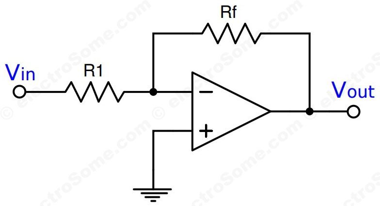
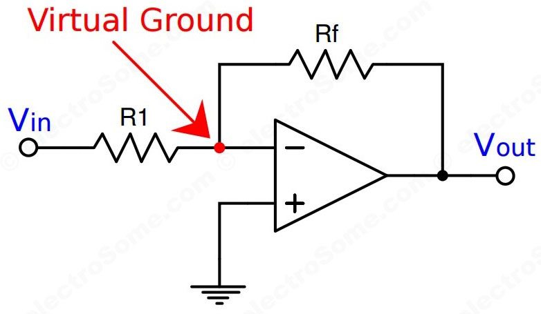
Virtual Ground Concept
Please read the article Virtual Ground – Opamp for more information about this concept.
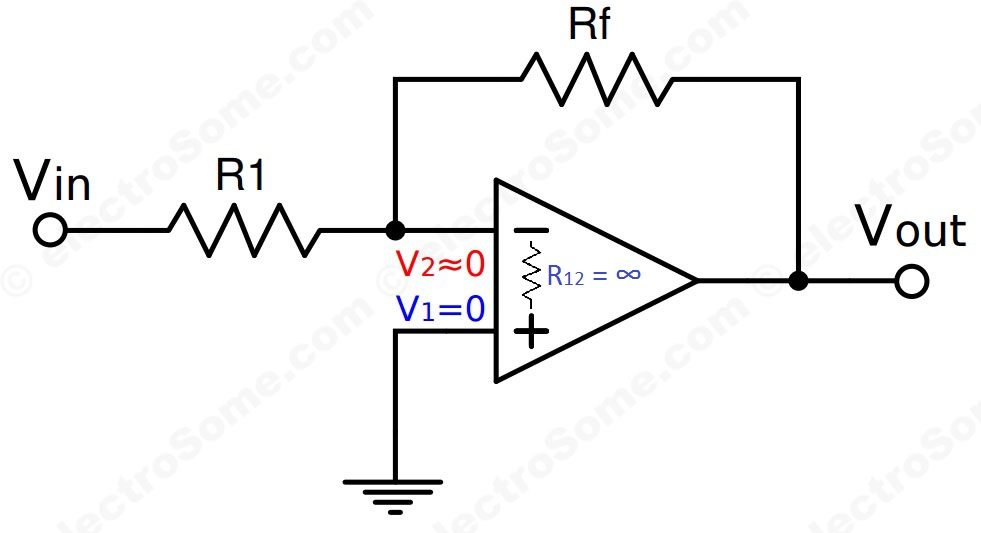
We already know that an ideal opamp will provide infinite voltage gain. For real opamps also the gain will be very high such that we can consider it as infinite for calculation purposes.
- Gain = Vo/Vin
As gain is infinite, Vin = 0
- Vin = V2 – V1
In the above circuit V1 is connected to ground, so V1 = 0. Thus V2 also will be at ground potential.
- V2 = 0
Voltage Gain
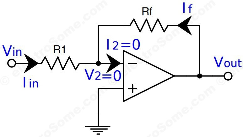
Ideally current flowing to the input of opamp will be zero. Thus according to Kirchhoff’s current law, Iin = -If, since the current flowing into the inverting terminal is zero.
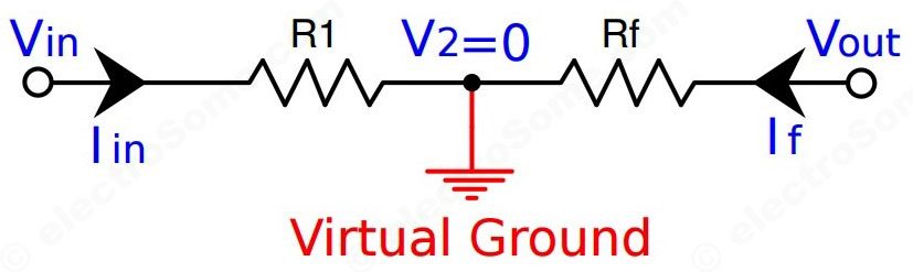
Thus,
- (Vout – 0)/Rf = (0 – Vin)/R1
- Vout/Rf = -Vin/R1
- Vout = (-Rf/R1) Vin
Closed loop gain, Av = Vout/Vin
- Av = -RF/R1
The equation of Vout shows that the circuit is linear in nature with a fixed voltage gain. Negative sign indicates that output is inverted or 180° out of phase with input. So this circuit can be used to amplify small signals.
Input Impedance
Determination of input impedance of inverting amplifier is important. Input impdeance plays a very important role for cases like signal source loading, impedance matching while multiple stages are coupled etc.
From above we can see that the inverting input is at 0V potential (virtual ground), so the input impedance is R1.
- Input Impedance = R1
Design Considerations
We need to consider following things while designing an inverting amplier with opamp.
- Gain Bandwidth Product : The product of gain and bandwidth of an opamp appears to be a constant. So don’t forget to check the available bandwidth when you are designing an amplifier with very high gain. You can get the Gain Bandwidth Product from the datasheet of the particular opamp you are using.
- Input Impedance : You have seen that input impedance of an inverting amplifier using opamp is same as the input resistance R1. So R1 should not be too small, remember that a good amplifier should have very high input impedance.
- Range of values for R1 and R2: Care should be taken while choosing values of R1 and R2 especially when high gains are required. We cannot choose a very low value for R1 since input impedance will get affected by it. Similarly we should not use very high value for R2, which will make the output unpredictable. You could use the rule of thumb vaule of 100KΩ for R2. So you could choose the maximum R2 somewhere near 100KΩ resistance.
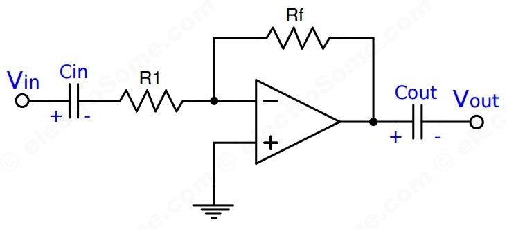
AC Coupling
As you already know, opamp will amplify AC as well as DC. So we should use AC coupling capacitors to block DC and bypass AC.
Why it is called Inverting Amplifier ?
As its name implies, output of an inverting amplifier will be 180° out of phase with input.

Transresistance Amplifier
Let’s see the transresistance amplifier circuit using opamp. It is also called Current to Voltage Converter or Transimpedance circuit.

As we see above,
- Is = -If
- Vout = -Rf * Is
So the output voltage is directly proportional to the input current.
High Input Impedance Inverting Amplifier
The main drawback of basic inverting amplifier is low input impedance, which is equal to R1. Suppose we need a gain of 100. As per practice we will keep 100KΩ as Rf, so R1 will be 1KΩ. 1KΩ input impedance is very low. Then we will be forced to increase the value of Rf to increase the input impedance, which will reduce the stability of the amplifier.
We can solve this problem by using a few additional resistors, which will create a high input impedance inverting amplifier.
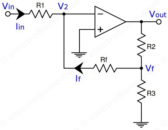
These additional resistors will further reduce the amount of feedback, which will increase the gain of the amplifier for the same value of R1 and Rf.
Ideally current flowing to the input of opamp will be zero. Thus according to Kirchhoff’s current law, Iin = -If, since the current through inverting terminal is zero.
- (Vin – V2)/R1 = (V2 – Vf)/Rf —————(a)
- Vf = Vout*R3/(R2 + R3) —————(b)
Applying (b) and V2 = 0 in (a)
- Vin/R1 = -Vout*R3/(Rf(R2 + R3))
- Av = Vout/Vin = -Rf(R2 + R3)/R1R3
- Av = -Rf(R2 + R3)/R1R3
So this circuit give us a wider range for selecting resistors. We can choose a higher value for R1 without affecting the feedback section.
Single Supply Inverting Amplifier
Generally opamps works in dual supplies like ±15V, ±12V etc. This enables chips to operate on analog signals with respect to ground without any level shifting. But it is not viable to use dual supplies in all cases. In those cases we can modify the circuit such that it will bias the input at half of the supply voltage.
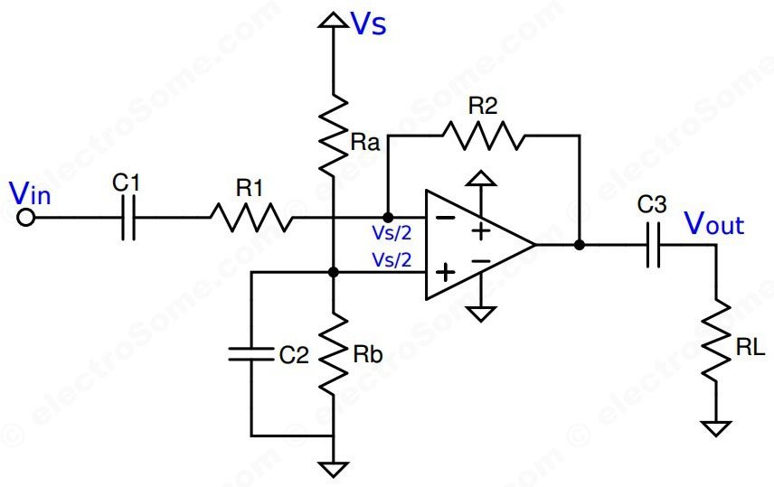
Thus the voltage will change with respect to Vs/2 instead of ground. Only problem with this circuit is that output voltage will be level shifted. So we need to decouple it to ground or use other level shifting circuits for that.
As you can see above, the operating point is set by resistors Ra and Rb. Capacitor C2 provides low impedance path for analog signals.
Calculator
You can use the following calculator for designing basic inverting amplifier using opamp.
Experiment
Let’s do an experiment.

- R1 = 4.7KΩ
- Rf = 10KΩ
- Gain Av = -Rf/R1 = -10/4.7 = -2.13
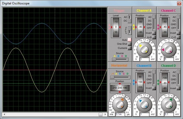
- Vin = 4V p-p
- Vo = 8.52V p-p (180° out of phase)


good